
 I’m not sure what it’s like in other parts of the country but here, in not always so sunny California, it’s been getting increasingly difficult to find a local gunsmith to do decent routine work. If you can find a gunsmith who will perform basic services, they more then likely specialize in one specific brand or, more typically, one specific model of firearm. So, increasingly, the solution to basic gunsmithing tasks can only be found hundreds of miles away at the end of 8 – 12 week shop backlog.
The out-of-the-box feel of the Bisley’s 3.5 lb.trigger was good. However, after some use the trigger pull did become rough, and the required release pressure started to wander. I thought I’d gather up as much technical information as possible relating to Ruger Blackhawk trigger rework, assess the cost of small tools and fixtures that would be required to perform the work, and maybe take a crack at doing the job myself.
“Bad” triggers are typical the accumulative effect of small burrs, rough parts, high/low surfaces, and improper alignment or seating of contacting parts. A lot can be gained from a simple clean up, but care must be taken to prevent permanently damaging the gun by improperly reworking any of these parts. There are several specialized tools that are required to accomplish this type of task.
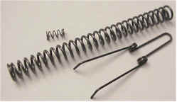 In addition to mechanical parts fit, springs play a role in trigger quality. Ruger utilizes coil springs, rather than fragile leaf springs, which are available in variety of rates for fine tuning a trigger job. Brownells Pro-spring kit for the Bisley includes: 3 hammer springs (center), a reduced power trigger spring (bottom) and an extra power latch pin spring (top). The factory hammer spring is 23 lbs., the kit contains springs rated at 17 lbs., 18 lbs. and 19 lbs.
Altering spring rates will not repair rough and poorly fitted parts, so generally the routine is to clean up related parts, improve fit and finish, and hopefully achieving the desired trigger pull. If the pull is clean, but still too heavy, spring changes could then be made to further reduce trigger pull. The downside of reduced power hammer springs, is reduced primer striking energy and increased lock time. In the extreme, these deficiencies could make the gun less reliable, and more difficult to hold on target.
Disassembly
There is nothing like taking a gun apart for the first time. On one hand there is the potential satisfaction of knowing you’ve mastered the complexities of a mechanical assembly, on the other is the risk of having to drop a box full of parts off at the gunsmith with the explanation a “friend” took the gun apart without your knowledge, and was unable to put it back together again. Of course, you could put it together, but you are really busy at the moment…
I typically take pictures of the gun as I disassemble, so I always have point of reference. I bag and tag related parts and keep short notes on anything that requires special attention. I know it sounds like a lot of work, but it really pays off in peace of mind from knowing you have a good shot at correct re-assembly. Guns are frequently not complex, just fussy about the placement and orientation of small parts.
I used a combination of the Ruger manual, as well as one of the Stoeger series of firearms exploded views books for guidance. I guess I had gotten spoiled by the Jerry Kuhnhausen .45 auto shop manuals or Lenny Macgill SIG disassembly video tapes, because neither of the documents covering the Ruger were particularly helpful. They seem to read like, “Step 1 Remove all the screws and pins. Step 2 – Remove all the parts. Step 3 – Reverse procedure to reassemble”. Fortunately, the single action is a simple assembly.
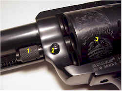
 The first step, after making sure the gun is unloaded, is to remove the cylinder and grips. The cylinder is removed by opening the loading gate, pressing the base pin latch (2), and pulling the base pin (1) forward and out of the cylinder (3). The cylinder will then roll out to the loading gate side of the frame. The base pin can be left in place for the time being, to help facilitate removal of other parts.
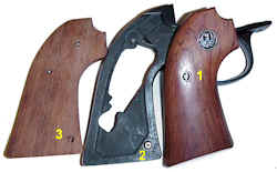 The grips are secured with one screw (1) and an alignment pin that passes through the grip frame (2) and fits into a hole in each grip (3). Care must be used when pulling the grips from the alignment pin. This is a tight fit and the pin will split the grip if the grip is pulled away from the grip frame at an angle.
As a general rule that applies to all firearms, correct fitting, hollow ground screw drivers should be used. “Correct” meaning a driver that completely fills the screw slot; width, top to bottom and side to side. Use of other types of drivers will gouge screw slots scrape away bluing and degrade the appearance of the gun. Use of incorrect drivers will also cause incorrect tightening of fasteners.
 A regular cross slot screw driver tip has a continual taper and only contacts the screw slot at the driver’s thickest point. A hollow ground screw driver has little taper in the contact area and parallel surfaces will make full contact in the slot, spreading the load over the largest possible surface area. Inexpensive sets of driver handles and wide selections of driver bits are available virtually any place tools are sold.
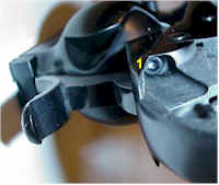
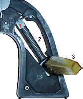 In preparation for removing the grip frame, the mainspring needs to be compressed and contained. This is done by pulling the hammer back, causing the hammer strut (1) to compress the mainspring (2) and the small eyelet at the end of the hammer strut to pass through the mainspring seat.
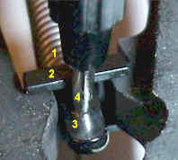 On the right: (1) mainspring, (2) mainspring seat (3) hammer strut (4) small tool pin passing through the hammer strut, preventing it from returning to the uncocked position.
With the mainspring locked in position, the grip frame pressure is unloaded, and the grip frame can be removed from the gun’s mainframe. The grip frame is retained at 5 points.
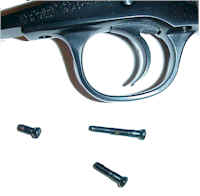 The first three screws pass through the bottom of the grip frame, one forward and two aft of the trigger guard. Notice each screw is significantly different. I got in the habit of storing these types of small parts in plastic bags with little notes that define location, orientation and anything else worth noting about the assembly.
One of these days I’m going to set up my video camera on a tripod and just tape disassembly on each new firearm. Current extended play tapes make this a viable technology and I can also edit out those periods of time when I might get off track a little bit.
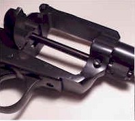
 The last two grip frame screws are at the top, and on either side of the grip (1). With the remaining 2 screws removed, the grip frame is pulled back and downward from the cylinder frame. This should be done over a flat clean surface as there are potentially two pins, the pawl plunger and cylinder-latch spring plunger that may fall free as the grip frame is pulled away.
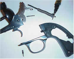 After the grip frame is pulled, the pile of parts should look like this. The mainspring is removed with the locking pin still in place, and the small parts are left right next to their related major assemblies, pending tagging.
The rest of the small parts in the trigger assembly are pinned to the cylinder frame, the pins are retained by the gate detent spring. So you basically flip the cylinder frame, trigger facing up, press down on the gate detent spring and rod until the trigger pivot slides out.
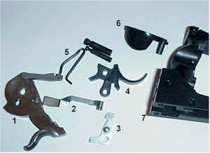 Once the trigger and hammer pivot pins are removed, you have what I like to think of as a small parts explosion. All and all there are not a lot of moving parts in a single action revolver which makes them seem much easier to detail disassemble than a 1911 auto.
The basic parts are: 1) hammer assembly 2) transfer bar 3) cylinder latch 4) trigger 5) gate-detent spring 6) gate 7) cylinder frame. Even if I wasn’t going over the trigger, the gun really needed to be disassembled and cleaned.
 Not sure exactly why, but the interior of the gun appeared to be packed with wheel bearing grease like preservative. There had been three attempts at flushing this gunk out without disassembly, using very strong pressurized degreasing solvents, but obviously none were effective.
Other than this gunk, there were signs of surface rust around screw holes in the trigger guard and some really rough castings. The rust in a new gun is typically the result of inadequate cleaning after the bluing process. Not a functional problem, but it looks bad.
I spent maybe an hour with toothbrushes, small picks and several types of solvent before grease and grime stopped oozing out of every recess and parting line. Afterward, I went over all of the parts associated with trigger and hammer travel with an eye loop and I could see all of the popular cost reduction approaches found in almost all moderately priced modern firearms.
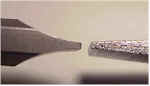
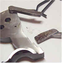
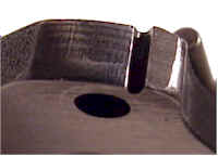 This is the trigger contact surface of the hammer. The surface should be free of tool marks, cuts should be parallel, or perpendicular to the side surfaces of the hammer, and chamfering should be uniform. Unfortunately, the externally visible areas of the hammer seem to have received the bulk of attention to fit and finish.
These rough and irregular surfaces create trigger creep, erratic trigger pull, high trigger pull, etc. They will also eventually damage mating parts and cause them to seat and wear unevenly.
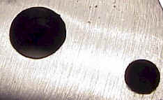 This is a side view of the hammer, which first appeared to be surface ground, but after measurement the finish appeared to be the product of a wire wheel or sanding disk. Parallel surface thickness bounced around between .293″ and .282″.
The large, irregular shaped hole is the pivot point for the hammer. It’s interior was rough and unfinished and the hole was not chamfered. This hole is really important, with the pin in place, it controls all of the alignment and concentric motion of the hammer against the trigger.
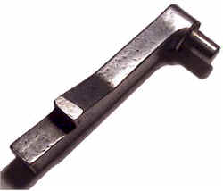 Outside of the cylinder latch, which appears to be a relatively high quality stamping and pressed pin, the rest of the buried parts are more like this pawl, rough castings that spent a lot of time in a tumbler. You can see how uneven the surfaces are, including bearing surfaces.
Some of this seems correctable, some will remain as is, an integral part of the product and product design. My approach will be to clean up only where there is adequate technical documentation and instruction to do so.
Polishing, reshaping of parts and refinishing, without technical guidance, could create safety and operational problems. Work, beyond simple cleanup, belongs with an experienced gunsmith who has a full understanding of the gun’s operation and design and has been trained to perform these expert tasks.
Tools and Fixtures
 Cleaning up of hammer and trigger parts cannot be done with unguided files, stones and emery paper. Small jigs or fixtures are required to hold parts in proper alignment, and to control depth and angle of any metal removal.
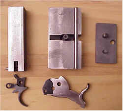
This is a set of fixtures I picked up from Brownells. They are, left to right, Wilson #15, #16 and #17. #15 is used to rework the Blackhawk trigger, #16 is used for hammer work, and #17 is to check contact and alignment of both parts, without having to completely reinstall them in the gun. Each fixture comes with a complete set of instructions showing how they are to be used.
 Precision metal removal, contrary to popular opinion, should not be attempted with a bench grinder, large rattail file or a Dremel. Finesse work is done with varying grades of abrasive finishing or polishing stones.There are many types of stones, across many grades, produced from many types of material.
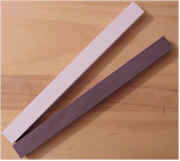
I picked stones to keep myself out of trouble, so I have nothing more abrasive than “fine”, and I complement that with one stone in “extra fine”. With these gems, I’d get tired before I could remove too much material.
I picked up a set of 6″x1/2″x1/2″ ceramic stones made specifically for this application, yes from Brownells. Apparently there is some great natural versus synthetic stone debate raging somewhere, which I am fortunately oblivious to. At issue are areas well beyond my level of skill and workmanship. The stones come with instructions – use water to reduce wear and stone loading, don’t leave abrasive material on finished parts, and a note that stones could be reshaped to work on specific guns or on specific parts of a gun.
The set of fixtures runs about $115, the stones about $30. The fixtures uniquely apply to the New Model Ruger Blackhawk family of firearms, which includes the Bisley, while the stones can be used virtually anywhere.
So with my favorite new gun in pieces all over my bench, small parts lined up in little fixtures, waiting for me to get up enough nerve to actually touch a stone to a part, I’ll take a break and double check my information before pressing on. I can also practice writing my letter, just in case:
“Dear Mr. Ruger,
I recently was able to purchase one of your fine revolvers from a person who obviously had little respect for the gun. It was in small pieces, some of which may have been damaged. Could you tell me how much it would cost to…..”
More “Ruger Bisley – Trigger Improvements”: Ruger Bisley – Trigger Improvements I Ruger Bisley – Trigger Improvements II Ruger Bisley – Trigger Improvements III
Thanks,
Joe
Email Notification