
 I absolutely agree with the author of a recent e-mail, who suggested that a white gas powered Colman stove, and heavy cast pot, is a better set up for wheel weight reclamation work than the Lee melter. The melter’s small reservoir and its need to be operated with clean material and pot, probably isn’t the best choice for messy reclamation work.
The unit at the left is a plumbers furnace, the tube connects to a propane bottle and there are 80 lb melting pots that could sit on top as the unit’s reservoir. Almost any form of cooking heat source can be used to melt lead, as long as the system will support the weight of the alloy. If you search the Internet for “camp stoves” you will find a large selection of single burner, heavy duty propane and white gas stoves that range from $40 – $140 and have the capacity to serve as a melter for mixing and making alloy ingots. You can also, of course, pick up a plumbers furnace. One other note, I misspoke in the last installment and said that lead can be absorbed through the skin. This is incorrect, however, lead can enter the system through small cuts, and also through ingestion of food handled by lead contaminated hands. If the gray smudges on that sandwich aren’t 10W-40, don’t eat it.
And now for something completely different…..
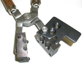
 This is probably a good place to begin, the central component of the casting process, the bullet mould.
Pictured at the right is an RCBS 2 cavity iron mould set, complete with instructions and handy storage case.
Each die set is marked with the cast bullet caliber, a nominal weight for bullets cast from the mould and the configuration of the bullet. As labeled, this mould will produce a .45 caliber bullet. Weight of cast bullets can vary with the density of the alloy being used; the closer the poured alloy is to pure lead, the heavier the resulting bullet. RCBS uses two different reference alloys when establishing nominal bullet weight. The reference alloy for pistol bullets is based on a 10 parts lead to 1 part tin mixture. For rifle bullets the alloy is 85% lead, 4% tin and 11% antimony; a mixture that will result in harder bullets. Harder bullets cast smaller than those more closer to pure lead alloys.
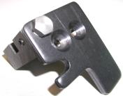
The machined and drilled flat stock at the top of this mould half is the sprue cutter. “Sprue” is kind of a general purpose word. In sand cast mould making vernacular, a sprue is the rod that locates the model in the sand during the actual mould making process. It is also used to identify the channel that fills the mould from outside and, finally, it is the waste cast material that fills the channel between the mould filling point and the cast object. In the context of this article, the sprue cutter removes the waste material from the bullet base after casting.
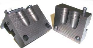 At the lower portion of the mould halves, just below the cavities, are the alignment dowel pins and corresponding guide holes. These locators assure exact alignment of the halves.
The horizontal score lines on the face of the mould halves are vents that assist in mould filling; the face of the halves are carefully ground flat in the manufacturing process, then air vent lines are milled across this surface. The lines permit the air displaced during mould filling to escape, yet are too fine to permit molten lead to flow through them under normal casting conditions. If there is a situation where alloy flows into these small vent passages, the typical causes are too high pressure flow into the cavity from a full lead pot, or too high tin content that excessively increases the alloy’s ability to flow into open spaces.
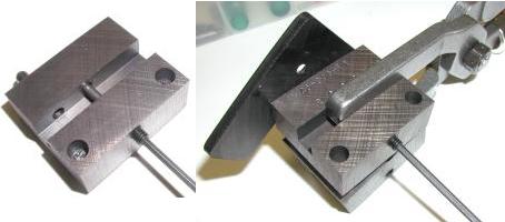
Being the quick study that I am, it took only a couple of cycles of holding the mould in my bare hands, to come to the conclusion I would need to buy handles. Only one set of detachable handles is required for multiple sets of moulds.
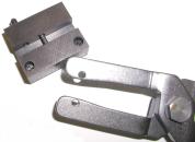
A slot milled in the sides of the mould halve provides a locating point for the handle shaft; the plier like clamp that holds the mould halves together. The shaft is affixed to the mould half with a locating pin, and the pin is held in place in the mould half by an Allen type set screw.
The handles fit loosely around the pins in a more or less floating arrangement, the mould halves are placed and held in alignment, and squared, by the mould dowel pins and machined flat mating surfaces.
When properly installed, the sprue cutter hinge will be facing the operator, which makes for easier operation after pouring. Do not attempt to grab human parts with this assembly, this may be fun but it generates a lot of gripping force. All of these components need to be seriously degreased before they can be used for casting.
Remember those ingots?
 In a prior installment, I was able to wrestle some wheel weight from local area yuppie SUV’s, and melt them down into ingots of more or less usable bullet alloy. I also, more or less, converted my shiny new furnace into a black blob ladened melting pot that is just waiting to dribble molten lead all over the work bench the minute it is plugged into an outlet. Ah yes, good times.
I chunked off a piece from my homemade ingot, about a pound and one-half worth, and tossed it into the melter. I placed the lead pot under the nozzle to catch any alloy that might dribble out while the pot came up to temperature. I set the regulator knob to 5, trying for a 700º F alloy temperature.

During the 20 minutes it took the ingots to melt in the solder pot, I disassembled the .45-70 mould and cleaned it with a non-petrol based cleaner. Moulds oxidize quickly if not protected, and rust in the mould cavities will blemish bullet surfaces, so a mould should never be stored without being sprayed with a rust preventative. Unfortunately, this means the mould has to be cleaned with a non-abrasive cleaner before being put back into service, and bone dry before attempting casting.
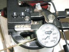
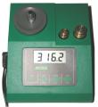
This looks a little congested, but this is the melter with a thermometer reading alloy temp, and the mould parked on the rim to preheat the mould. The mould should never be immersed in the molten alloy, but rather heated by the outside rim or alloy pour.
Getting to this point is relatively straight forward and the steps are easy to define, concluding with fluxing the dross and removing obvious impurities. The next step in the process is a little more subjective and a bit of experimentation may be necessary to get the desired results.
I began by resting the bullet mould on top of the ingot mould, pouring straight into the sprue hole. The result was incomplete cavity filling and an irregular bullet surface.
I began holding the mould just below the nozzle, and angled away at about a 45º angle, turning it bullet nose down as the mould filled. When there was a notable overflow from the first cavity, I repeated the angled positioning and filling with the second cavity; the result was much better. The driving bands were more cleanly defined and some of the fine line detail became visible. Still, the production parts lacked uniformity.
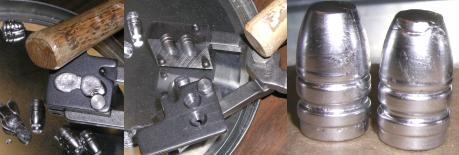
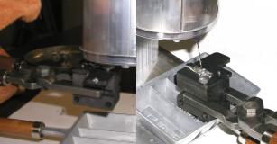
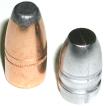
Above, the first frame is the sprue cutter at the top of the mould being tapped open with a hardwood hammer handle 3 – 5 full seconds after filling the mould. Metal tools should never be used to strike the mould or the cast parts as they could cause permanent damage to either. In the second frame, with the sprue cutter rotated out of the way, I tapped on the handle hinge pins to coax the cast parts from the mould. The mould should not be struck directly to free parts and, again, metal tools should never be used to strike any part of the mould-handle assembly. You can see the voids in the bullet tip at the right in the past frame, and porosity in the base of the bullet to the left. Neither bullet passed inspection and, based on the reference material available to me, I thought the problem might be a not adequately warmed mould.
I continued experimenting with pour angles and distances, and I noticed a lot of the surface imperfections began to disappear, and small mould detail like a parting line was now visible. Periodically I’d drop the imperfect bullets and sprue back into the melting pot, let them blend back into the alloy, and then pour fresh bullets.
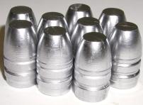
The bullets to the left have not yet been sized, but they were well formed as they fell from the mould. Oh, one note, the Lyman “Cast Bullet Handbook” suggests placing some rolled fabric on the bench top to catch the bullets as they drop from the mould to prevent the bullets from deforming. I held the bullets in the mould for approximately 10 seconds after the sprue was cut, then dropped them on an inverted foil pie plate. The plate surface gives and dampens the fall without damaging the soft alloy but, unlike the fabric, it doesn’t smolder.
 Okay, so now I had these not yet sized bullets made from reclaimed wheel weights. Considering all of the handling and process work, I figured they would be plus-minus a bunch of grains from one bullet to the next, so I thought the next logical step would be to weight them. I was also interested to see what final weight this alloy would reach in the 300 grain mould. As noted previously, the RCBS nominal weight of 300 grains was based on an alloy of 85% lead, 4% tin and 11% antimony. I also took the liberty of weighing some jacketed bullets so there would be some basis for determining typical consistency of weight from one bullet to another.
| Sample | Cast Grains |
Variance to Avg. |
Jacketed Grains |
Variance to Avg. |
| 1 | 316.8 | 0.0 | 350.2 | -0.7 |
| 2 | 316.3 | -0.5 | 353.3 | 2.4 |
| 3 | 317.8 | 1.0 | 350.6 | -0.3 |
| 4 | 316.2 | -0.6 | 351.0 | 0.1 |
| 5 | 316.9 | 0.1 | 350.1 | -0.8 |
| 6 | 316.4 | -0.4 | 349.9 | -1.0 |
| 7 | 318.6 | 1.8 | 350.0 | -0.9 |
| 8 | 316.9 | 0.1 | 350.2 | -0.7 |
| 9 | 316.3 | -0.6 | 351.2 | 0.3 |
| 10 | 315.8 | -1.0 | 352.2 | 1.3 |
| Avg. | 316.8 | – | 350.9 | – |
| Spread | 2.8 | – | 3.4 | – |
| % Spread to Avg. Wgt. | 0.8 | – | 0.9 | – |
In comparing cast versus jacketed bullet uniformity, cast performed marginally better than the Speer Hot-Cor sample, but both types varied by less than 1% within each respective population. I did a spot check on other bullets of similar bore capacity and weight with similar results.

I was feeling like I had overlooked some important information. I thought I would take one more run at the entire process, start to finish, and see if I could spot what I had missed during the first attempt. I was particularly interested in seeing if I could identify critical temperatures for the pot and mould during the process. It’s good to work around tech people, they always have odd equipment nearby. In this case it was a Fluke 65 non-contact Infrared Thermometer, with a reading range of -40ºF to 932ºF and a laser spotter.
This meter is great for reading gun barrel temp, as well as mould temp, but it is not a good tool for reading surface temperature from melted alloy, unless there is a lot of dark crud on the surface. Infrared thermometer accuracy is based on Emissivity, the target object’s ability to emit infrared energy, and most units are calibrated to be most accurate when sensing from a flat black surface.
For reading a bright stainless barrel, a target of removable magic marker can be placed along the barrel for data collection. Unfortunately, it’s tough to put a marker or black tape on the surface of molten alloy. I was able to get within 20ºF of an RCBS mechanical thermometer 740ºF reading, 2.8% difference, just by reading off the dark gray dross center. Actually, this may have been right on, because the RCBS unit was reading below the surface, while the Fluke thermometer was reading at the surface. Other readings taken from black surfaces like the mould halves verified right on with a contact thermometer readings.
I started the new cycle with clean lead, which resulted a melting process with no smoldering fumes. Reading from the black rim of the melter, the temperature began at 66ºF, climbed to 329ºF in 5 minutes, reached 420º in another 5 minutes, and broke 445ºF 10 minutes later. At this point the alloy began melting at the bottom of the pot which put this contact temperature above 621ºF. 35 minutes after the process started, the temperature had been stable for 10 minutes with the rim at 635º and the solder at 740ºF; 720ºF read by the Fluke and 740ºF with the RCBS mechanical thermometer. Basically, I learned to not cast bullets for the first 30 minutes after powering up the melter filled with hardened alloy, or the temperature would vary and yield inconsistent results.

 Because I began with clean lead alloy, all I needed to do was pull the weight clips and the material was clean, even before fluxing. I dropped in a little Marvelux, skimmed off a small amount of impurities, then began casting bullets.
I had placed the mould on the rim of the melter prior to the first pour in an attempt to preheat. The outside block temperature of the mould was 90ºF for the first attempt, and the result was two bullets that were very porous and only partially formed.
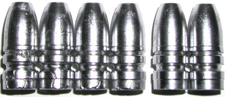
The bullets above reflect 5 casting cycles and 5 mould temperatures: 138ºF, 146ºF, 163ºF, 190ºF and 214ºF. The first four examples are one from a set of two cast at each indicated temperature. The last two bullets, far right, are a set from the last pour; they were completely formed and near perfect. I repeated this step again with a cold mould and got the same results, I now know I need to have the mould halves above 200ºF to get decent bullets.
I ran the same weight consistency check with the lighter .35 caliber cast bullets and got very similar results, proportional for this weight. The .35 caliber bullets were easier to cast and, at least by appearance, they were much easier to produce than the .45 caliber bullets.
The .35 caliber jacketed bullet weight results were quite different from the .45 results, so I went on to evaluate jacketed bullets from a second manufacture to shore up, or discard, my assumptions made from the first comparison. The 200 grain jacketed bullets were Hornady Interlock, the 225 grain were Sierra Game Master SPBTs.
| Sample | Cast Grains |
Variance to Avg. |
Jacketed Grains |
Variance to Avg. |
Jacketed Grains |
Variance to Avg. |
| 1 | 207.2 | -0.4 | 199.8 | 0.0 | 224.7 | 0.1 |
| 2 | 207.8 | 0.2 | 199.5 | -0.3 | 224.4 | -0.2 |
| 3 | 207.5 | -0.1 | 199.6 | -0.2 | 224.9 | 0.3 |
| 4 | 207.7 | 0.1 | 199.9 | 0.1 | 224.7 | 0.1 |
| 5 | 207.9 | 0.3 | 199.7 | -0.1 | 224.4 | -0.2 |
| 6 | 207.4 | -0.2 | 199.8 | 0.0 | 224.6 | 0.0 |
| 7 | 208.2 | 0.6 | 199.7 | -0.1 | 224.5 | -0.1 |
| 8 | 207.4 | -0.2 | 199.8 | 0.0 | 224.5 | -0.1 |
| 9 | 207.7 | 0.1 | 199.8 | 0.0 | 224.4 | -0.2 |
| 10 | 206.9 | 0.3 | 200.1 | 0.3 | 224.5 | -0.1 |
| Avg. | 207.6 | – | 199.8 | – | 224.6 | – |
| Spread | 1.3 | – | 0.6 | – | 0.5 | – |
| % Spread to Avg. Wgt. | 0.6 | – | 0.3 | – | 0.2 | – |
The result was that jacketed bullets were more consistent in weight than cast bullets, of course I have no idea how many bullets are pulled out by manufacturers as the result of production weight checks.
Summary
If I were to continue casting bullets I would make a few changes to my current set up. I would look for a plumbers furnace to recycle wheel weights and to mix alloy ingots. I would upgrade ingot moulds, lead pots and ladles to a larger size and with heaver construction. I would probably make due with the Lee melter if I picked up the furnace. If not, I would look for a furnace with better temperature regulation and a much larger diameter reservoir and greater capacity. I would scale weigh all bullets and determine a viable weight variance spec to live by. I still have one more section to cover, bullet sizing and lube, and heat treating for hardness. When I wrap this topic up, I will summarize all associated costs.
More “Casting bullets and selecting fire extinguishers”:
Casting bullets and selecting fire extinguishers Part I
Thanks
Joe
Email Notification