
 Just a note that both Brownells and Midway USA recently added the Power Custom line to their catalog. Power Custom offers parts for a variety of firearms, however specifically related to this week’s topic, they produce improved components for the Ruger single action; hammer, trigger, springs, custom pawl that allows 2 way cylinder rotation when loading. There is also a trigger job kit that include all components necessary to bring trigger pressure into the 2.5 – 3 lb. pull range.
Ruger Bisley – Trigger Improvements part III and conclusion
I had a one hour window of opportunity and I attempted to finish the Bisley. The parts rework had been completed, so I thought I had plenty of time to reassemble the Ruger, photograph the process and, if necessary, do any last minute tweaking with springs. Bad decision. The work room was a mess, everything pulled to the middle of the floor to make room for dry wall work and painting, so every time I needed a tool, it was buried under a tarp someplace and I had to go scrounge around to find it.
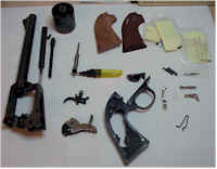 I started off with parts cleaned and oiled as appropriate. I worked on top of a clean sheet of white paper so it would be easy to see small parts, particularly tiny springs that tend to fall out when least expected.
As you can see, in total there are not a lot of parts in a single action revolver. If you’ve been able to work your way through the process once or twice, the Ruger documentation is easy to follow, but I think that’s suppose to work the other way around.
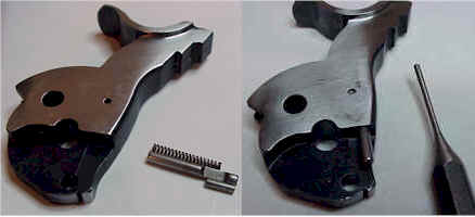 Assembly began with putting together one of the subassemblies, the hammer and the small hammer plunger and spring.
The spring is dropped into the recess in the hammer, the plunger is placed in the recess, leading with the notched end, then the plunger is depressed until the notch clears the pin hole in the side of the hammer. The pin is then driven through the hammer where it retains the plunger under spring pressure.
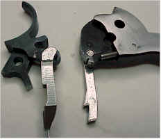 The boss on the pawl slips into the hole adjacent to the hammer’s full cock notch, and the transfer bar is similarly attached to the upper opening in the trigger. At this point, nothing actually holds these assemblies together, but they need to be in this configuration to assemble them into the cylinder frame.
The next few steps entail fitting parts through the bottom of the cylinder frame. The frame can be flipped over and rested on the gun’s sights while this work is being performed. If there is any heavy duty cleaning to do on the frame, this the time to do it. There are a lot of places for gunk to accumulate and no easy way to get to these areas without tear down.
 The hammer and trigger have to be somewhat sandwiched together and lowered into the frame simultaneously – more difficult to say than do. There are obvious channels and openings for each part to slide into so they will either fit correctly, or not fit at all.
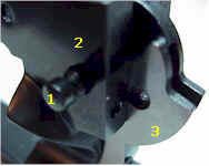
The Hammer pivot pin (1) is slipped through the frame (2) and passes through the hammer (3). It will slip out very easily until the grip frame screws are installed later on in the process. A couple of other parts need to be installed before the trigger can be pinned into place.
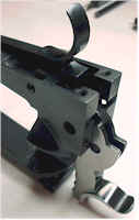
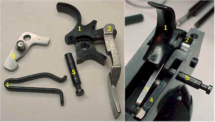 1 & 2, the trigger and transfer bar, are dropped into the slot in the cylinder frame. The boss on 3, slips into 4 (cylinder latch into the gate detent spring), and both are dropped into their respective slots in the cylinder frame.
The gate detent spring’s open end is compressed, and the trigger pivot (5) passes through the frame, over the spring, through the trigger, and into the other side of the frame. I know it looks like a blob, but these parts actually go together easily and fit into enough frame slots that it would be almost impossible to install them incorrectly.
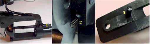
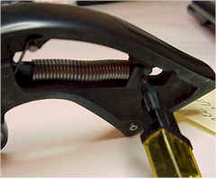
In preparation of the grip frame installation and final assembly, the base pin assembly (1) is installed to prevent the transfer bar from hitting the firing pin while working the assembly, the pawl spring and plunger (2) are installed in the cylinder frame, and the cylinder latch spring and plunger (3) are installed in the grip frame.
 The grip frame will slide into place, with all parts correctly positioned, as long as the trigger spring is unloaded by slipping the spring hooks off of the cross pin in the grip frame. If you attempt to install the grip frame without completing this step, you will continue to try, until you finally give up and perform this step correctly.
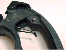
The trigger spring rests on top of the tab projecting from the rear of the trigger. It’s function is to keep the trigger loaded in the forward position.
The mainspring is placed in position in the grip frame, but the pin that is holding the spring’s tension is left in place until the grip frame in completely secured to the cylinder frame. As the grip and cylinder frame are fit together, the hammer is rotated back until the end of the hammer strut (the part that the mainspring is wrapped around) fits into the slot in the hammer.
The final movement in assembling these parts requires a little extra care. It’s easy to collapse or pinch the small plunger springs between the frames as the larger parts are screwed together. All five fasteners were started, then progressively tightened. Each of the three lower grip frame screws are unique and must go to the correct location. As an example, the right rear screw is extended and serves a second purpose of retaining the hammer pivot.
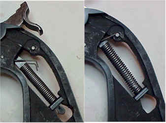 One the grip frame is in place and secured, the hammer is moved to the full cock position, compressing the mainspring, and allowing the pin that has been retaining the hammer strut to be removed.
The trigger spring is then hooked at the cross pin in the upper part of the grip frame and the hammer can be lowered.
When I got to this point, I was out of time and rushing to get everything wrapped up. I should have stopped.
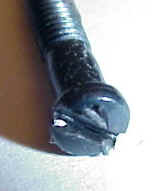
I had grabbed the wrong driver and chewed up one of the grip frame screws. I tend to get a little crazy about damaged hardware and hacked up parts. This was one of those deals that unfolds in slow motion, cranking away on an incorrect size screw driver until the screw head just gives way, along with the finish, leaving you wishing you could take back the last 30 seconds.
I continued on and wrapped everything up, stuck a trigger scale in place and….4 lbs., heavier than the original factory pull. Maybe a little cleaner on release, but something was wrong. So here I was, out of time, feeling really guilty about some poor workmanship, and now I knew it was time to take a break.
I waited a full day before returning to the project. I ordered a set of replacement grip frame screws (actually 2 each), and I ordered a replacement hammer and trigger, just in case. Then I slowly disassembled the Ruger, looking for improper points of contact, incorrectly assembled parts, anything that might be out of the ordinary and could be contributing to the problem. I actually found two problems.
The first was a dry contact surface. Not sure how I missed it, but the surface contact at the full cock notch and trigger sear was dry. The second problem was a small burr to the side of the 45 º clearance cut I made on the leading edge of the sear that seems to come in contact with the rough interior of the cylinder frame on the trigger return. I cleaned up the part, lubed the trigger / hammer assembly, reassembled the gun…3.5 lb. trigger pull and smooth.
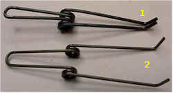 I thought I might have to try a lighter trigger spring, but I was committed to not changing to a lighter mainspring. There is a pretty obvious difference between the factory trigger spring (1) and the Wolff spring (2), with the Wolff spring providing a 30% reduction in rate.
The spring retaining pin popped out with a small punch, and the replacement spring was a drop in.
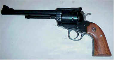 The trigger pull settled in at slightly less than 3 lbs., with no creep or rough spots. Cocking the hammer and pulling the trigger felt a lot more precise. The most important achievement is clearly illustrated by this picture, one complete gun and no “extra” or left over parts.
I think the improved trigger pull and feel made a big difference in the way the gun shoots. The Bisley use to point like a club, and the original long rough trigger pull didn’t help to reduce that impression. With the cleaned up trigger, the target group size remained essentially the same, but the gun was easier to shoot, and getting on target and firing was a much faster process.
I’m really glad I took on this project. I learned a lot about the Ruger and the way it works and the gun worked better at the end of the project then in the beginning. I didn’t have to send the gun anywhere, so I didn’t have to incur the cost of shipping and insurance, or wonder if the gun would disappear in transit and end up on an anti-gun TV show, or the subject of a Congressional hearing. Probably of greater importance, I didn’t have to settle for someone else’s opinion of a correct trigger pull and feel. I was able to work on it until I liked it, and I had the control to alter the outcome.
The Wolff parts were inexpensive and offered a good range of components for tuning, same as they have been in use in my auto pistols. Ruger parts, purchased through Brownells, were inexpensive and readily available. Most piece parts, these days, seem excessively expensive and not always easy to locate. I have a few other parts to change on the Ruger and I’m looking forward to the tasks. When I’m all done hammering away, I’ll treat it to a new finish and some items to improve it’s appearance.
While I generally believe jigs and fixtures should be used to control critical work, I believe the Wilson fixtures were did not make a significant contribution to the quality of the work, or make the combined tasks any easier. Slots were cut incorrectly, pins were oversized, blocks were improperly relieved to the point they could not be used as received with production Ruger parts. I thought the fixtures should have been surface hardened, at least harder than the parts being reworked. Setting those issues aside, they just seemed to be of less than optimal design.
There was nothing in the hammer fixture to guide a parallel cut with the stones. There was nothing that set a cut depth for the full cock notch step. There was nothing that controlled the angle of the notch when cut with a triangular stone. Actually, I could have done just as much in locating and controlling the rework with a simple bench vice. The trigger fixture wasn’t better, with no way of limiting the sear surface cut, or to control the angle cut at the front of the sear. There was nothing to guide the stone to remain perpendicular to the trigger when working on the sear.
The sear block for checking trigger/hammer engagement was okay, but nothing would replace the actual firearm for checking alignment and contact. Knowing what I know now, I would be a lot more careful in the selection of a set of fixtures, and they would have to do a lot more than just hold the part in a vertical position. In this case, I think real documentation covering dimensions and desired finish could have replaced the need to use these fixtures, and I could have saved a substantial amount of money.
The Bisley is going back in the box for now, and we’ll see if we can’t change up to something a little different.
More “Ruger Bisley – Trigger Improvements”: Ruger Bisley – Trigger Improvements I Ruger Bisley – Trigger Improvements II Ruger Bisley – Trigger Improvements III
Thanks,
Joe
Email Notification