 I’ve changed the book reviews and listings for gun related firearms and I am starting to include other sources besides Barnes & Noble. I started to run into too many instances where books were listed as “requires special handling”, or “book out of print – special order” when I knew, for a fact, books were readily available, at lower prices, from numerous other legitimate sources.
I went through and sorted out the site, including most of the archive pages. I had noticed some detached links and missing images that were caused by my moving things around on the site. If you run into similar problems in the future, please just let me know and I’l get the problem squared away.
Ruger Bisley – Trigger Improvements II
I just wanted to note as a reminder – The basis for this short series of articles was to see if an amateur firearms enthusiast could reasonably complete a trigger job on a Ruger single action revolver. The text is a reflection of my understanding of the task, and is to be considered an experiment until completed and the gun checks out for proper safety and operation. The last installment will be a summary of the process and correction to and information or early conclusions that might have been in error.
Two steps forward, one step back. I had a Ruger manual, a disassembly guide, a copy of “Gunsmithing: Pistols and Revolvers”, and the documentation that came with the Wilson hammer/trigger rework fixtures – none of this provided enough information for me to begin work on any of the parts. I don’t know if single action revolvers are as sensitive to alterations as 1911 design pistols, but trigger work can impact a gun’s safe operation, and quality of function.
For a gun design that’s been around for a very long time, it’s difficult to locate anything published on Ruger’s single action revolvers that would offer enough detail to be useful in making modifications. A person working on any modern auto pistol or double action revolver could select from an almost endless list of publishers and authors. In fact, if I wanted to work on any Ruger double action, auto, .22 pistol or rifle I could select from books, charts and video for guidance.
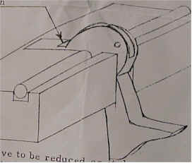 I was disappointed with the documentation that came with the Wilson fixtures from Brownells. I suppose the argument could be made that these tools are typically used by experienced gunsmiths, but I think that’s not a valid excuse for the manufacturer.
Machinists, and any other person involved in the modification of parts, requires accurate drawings, illustrations and explanations, before jumping in and hacking up parts. Whoever purchases the fixture is entitled to a quality representation of how it should be set up, and to what specs parts should be reworked.
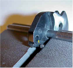
The picture on the right is the actual part and fixture, supposedly represented by the sketch. Er..if that drawing illustrates how to properly modify that little notch (1) I must be missing something. The text goes on to advise of steps such as, “whet with 400 – 500 stokes.” I just don’t know how the number of stokes would get anyone to a specific finish, dimension, parallel surface, etc.
It would be nice if the folks who sell these products spent a couple of hours writing some decent representation of its intended use, better still, maybe include a couple of “before and after” pictures of parts and proper setup, maybe even highlighting critical areas.
I assembled and disassembled the Ruger several times. I put parts in the fixtures and worked the action without springs in place. I took a look through several reference books that illustrated theory of operation for the single action revolver until finally it all sank in, and I was comfortable enough with the operation of the gun to understand the purpose of the modifications and the projected results.
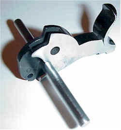 I started the rework setup with the #16 jig for the hammer. The fixture has two parts; a machined block and a steel pin. The pin passes through the hammer pivot opening, and is used to align and properly position the hammer in the block. The pin was a tight fit, not a press fit, but a snug fit, which seems right for keeping parts aligned.
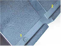 There is a groove in the top of the fixture the pivot pin rests in during the rework. There are set screws that pass through the bottom surface of the block and project into the groove. The distance from the projecting screws to the upper surface of the block should be .101″, to properly locate the pin and hammer. These dimensions should be verified before the fixture is used. Checking with a depth mic, one was right on at .101″, the other was .005″ low.
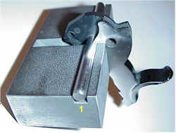 Combining the two fixture parts with the hammer should result in something that looks a lot like this. Unfortunately the hammer, when mounted to the pin, wouldn’t rotate through full travel without making contact with the block. This contact forced the pin away from the block on the left side (1), moving the hammer out of proper position.
It looked as though the hammer plunger was bumping against the set screw in the center vertical groove in the block, forcing the hammer out of position. I removed the hammer plunger.
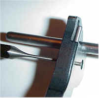 Removing the plunger assembly is a pretty easy deal. You hold the hammer in one hand, hold a small punch to the plunger retention pin with the other hand, then use your other free hand to tap the pin out. Yes, I know.
The plunger is spring loaded, so you want to be careful it doesn’t pop out and fly across the room. On the other hand, the plunger spring may not fall out when the plunger is removed, but it will drop out while your working on the hammer, and immediately roll under an immovable object.
With the plunger removed, I dropped the hammer back in the fixture, but it was still binding against some surface of the block. A little further investigation, and I could see the contact was with the lower right front edge of the block’s vertical slot.
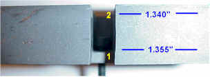 You can see how crooked the fixture slot was cut with (1) shifted toward the left and creating the interference. I do not believe this shift was to accommodate an offset in the hammer, and a .015″ machining error was enough to prevent proper use of the fixture.
Most fitting and filing fixtures are made for production, and are surface hardened to prevent them from prematurely wearing in normal use. I thought I might just exchange the fixture for one that wasn’t defective because I thought the hardened surface would make metal removal difficult. It took exactly 4 stokes with a fine file to clear the .015″ problem, and arrive at the conclusion – the fixture was not surface hardened.
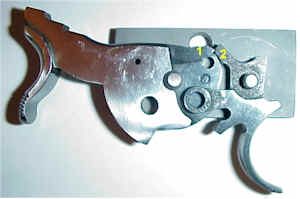 If this were a 1911 type auto, we’d be looking for sear/hammer engagement. The single action Ruger incorporates the sear function into the trigger.
The #17 fixture, a sear block, permits trial fitting of parts and checking for engagement between hammer and trigger, without having to constantly reassemble the pieces into the gun.
The rework objective is to get .012″ – .014″ engagement at (1) and (2), and to reduce friction.
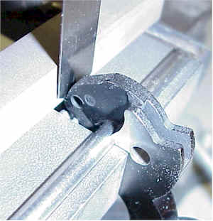 The fixture instructions suggested adjusting the hammer’s full cock notch .030″ “or more” above the fixture’s surface, placing a square India stone against the hammer, and measuring the gap with a feeler gauge.
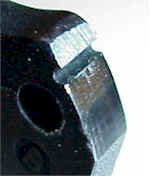 I tried the stone and feeler gauge method, and I verified with a dial indicator. There was .022″ engagement with my hammer, trigger combination and, and the full cock notch contact areas were rough and uneven.
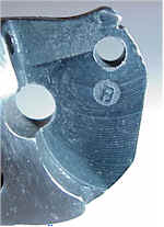 In the front view photo, you can see how uneven the part was ground and how rough the metal was at the groove, or point of contact. This condition would create high trigger pressure, creep and a rough feel. In the first installment of the article, I noted I had purchased a fine and extra fine square stone. After I got the fixtures and walked through the rework, I realized I needed a triangle shaped stone to clean up the full cock notch.
 I ordered a Norton India stone from Brownells. Unlike the first two ceramic stones that use water for lubrication, the new stone uses honing oil.
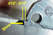 With the hammer mounted securely in the fixture, the full cock notch is adjusted down to between .012″ – .014″. This is done by stoning the area of the hammer immediately below the notch, measuring frequently as the work progresses. It is important for the stone to be kept parallel to the surface to insure the .012″ – .014″ dimension is held all the way across the notch, insuring a complete contact surface with the trigger sear.
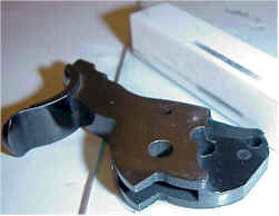 I found the area immediately under the full cock notch was relatively easy to hold parallel while stoning, but it was difficult to blend the resulting flat into the the area further down from the notch.
I put a sheet of glass on the bench, placed the hammer on the glass with the thumb grip area hanging off the edge, so the hammer was resting on it’s flat side surface. Then I drew the stone over the surface I wanted to blend and keep parallel. Worked out really nice and I used the same technique on some of the other clean up.
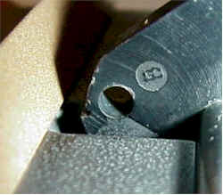 Cleaning up the actual full cock notch was a concern because the Wilson fixture set the hammer at an odd angle to the surface that would guide the triangular stone. I was concerned the angle of contact would be off and reduce the surface area supporting the cocked hammer.
The notch is tipped down, toward the fixture surface and, while the stone is held parallel to the fixture surface. I kept the notch approximately .002″ above the fixture surface, used a large magnifying lens, and exercised a great deal of care with the stone. It only took a couple of touches to remove the manufacturing tool marks and clean up the notch.
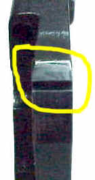 This is the finished hammer, or at least as finished as I could get with my limited skill and experience. The area in the yellow circle was stoned to reduce the the full cock notch to .014 “, the notch was cleaned of tool marks and made parallel to the trigger sear. The angle of the notch was not changed in any way.
The surface immediately above the notch has been smoothed, but this is not really critical since it is not a contact surface, but the trigger sear drags across this surface under load, so surface should be uniform
Reducing the contact area of the full cock notch and smoothing that surface are important steps. The quality of finish will have a direct impact on trigger pull. Under spring load, with low mechanical advantage, a small burr, or an area worn rough, can feel like you’re pulling a trigger over gravel
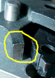 On the left is a close up of the trigger and hammer set placed on the sear block so engagement could be checked. Throughout the rework process, a candle was used to blacken contact surfaces, then the parts were cycled and rub marks were inspected as an indication of proper engagement.
If you look closely, you can see a vertical mark running down the face of the trigger sear. This is an indication of full contact and parallel surfaces.
This particular check was done after the hammer work was completed, but prior to any work being done on the trigger.
Next, the Wilson #15 fixture was used to accomplish the rework on the trigger. As received, the trigger would not locate correctly in the fixture. When the sear position was set correctly, the tab on the side of the trigger contacted the rear surface of the fixture, preventing the fixtures locating pin from being installed.

#15 is a simple rectangular block, slotted, cross drilled and fitted with a set screw. The trigger slides into place with the sear pointing straight up. The set screw is adjusted to place the sear surface parallel to the surface of the fixture. As illustrated to the far right, the clearance slot was inadequate and did not allow the trigger to be properly aligned. I removed a small amount of material from the recess, maybe .020″ and the trigger fit in place correctly.
 On the left is the finished trigger. When completed, it mated correctly with the hammer full cock notch, fully across the face, and both part surfaces were parallel to one another. The trigger was a little difficult. There were many deep tool marks and the fixture did little to help create a parallel face. I found it best to run 50 or 60 stokes with the stone, then turn the fixture around, and make the next 50 or 60 strokes from the other direction. The final cut was to put a 45 degree bevel across the sear, opposite the engagement edge.
I’m going to break at this point, with all of the parts completed, and only reassemble and live testing remaining. Should have it all wrapped up next time around. Hopefully, the results of the trigger job will be quantified and I may even have some suggestions for a better set of jigs and fixtures.
More “Ruger Bisley – Trigger Improvements”: Ruger Bisley – Trigger Improvements I Ruger Bisley – Trigger Improvements II Ruger Bisley – Trigger Improvements III
Thanks,
Joe

Email Notification