As a byproduct of the .45 Super project, I decided to pursue the issue of recoil spring selection a little further. So as an update, I decided to see if I could build a functional spring tester, collect some data on common spring selections, and test some of the quick fixes and modifications that are routinely suggested elsewhere. The data and results follow the construction portion of this article.
The topic of recoil springs in semi auto pistols generally covers a lot of ground. Springs are adjusted to compensate for varying loads and pistol configurations. Springs are selected to replace fatigued components. Springs are changed in support of a variety of guide rods and recoil spring plugs. Springs are changed to cure feed, extraction and ejection malfunctions. So we pick up a package of heavier or lighter rating, install them and hope for the best. Personally, I wanted a way to measure springs so I knew what real rate I was installing, or discarding, or had been working very reliably in my guns with specific loads. There might even be a time when I wanted to experiment, and be able to quantify the result of changes made.
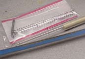 It’s convenient to start a project with no more than a concept, then let whatever materials you can find around the workshop dictate the final design. I knew a compression spring would need to be held captive in some sort of fixture, would require a simple means to compress the spring as it was held in the fixture, and a way of measuring both the force required to compress and the distance over which the compression occurred.
The above criteria led me to a length of rigid clear plastic 1/2″ ID tubing, a similar length of 1/2″ OD hardwood dowel and a section of clear plastic ruler. Based on recoil springs always being in the 6″ – 7″ range, I cut each of the parts to an even foot. A hacksaw and a little patience works great on polyvinyl.
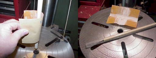
The piston would have to move freely in the cylinder, without being too loose, to prevent friction from being a significant factor when reading compression resistance. I chucked the dowel in the drill press, cut the speed down to the low 500 RPM range, and ran some 350 grit sandpaper across the surface until the dowel moved freely within the tubing while maintaining a relatively close fit.
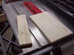 The next step would be to fabricate a frame to mount the tubing with one end closed off to contain the compressed spring, and the other left open to permit free movement of the dowel while compressing. I dug around and came up with some board made of glued up 1″ wide pine strips. As a laminate it was very straight, and pretty sturdy.
I figured 2 1/2″ would be wide enough to provide a good grip when testing. So I cut a 2 1/2″ wide piece for the back of the gauge, allowed 1/2″ for the tubing width, then went on to cut 1″ strips to locate the tubing from either side.
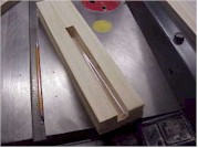 width=”179″ height=”134″ align=”right” border=”0″>With the sides cut, I dropped the tubing into it’s approximate finished position, marked off the distance to the top, and cut a piece that would reside between the two sides and provide a cap for the tubing.
At this point the mount board was well oversized, as was the tubing, but I thought I would go back as I finished the assembly and trim it all down to the smallest reasonable size. The intention was not to secure the tubing’s position with the frame.
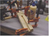 Humm….maybe a little bit of a clamping overkill. I used a heavy duty exterior glue that would be resistant to some of the solvents that routinely make their way to the work area. I used a lot of clamps to make sure the contact was right and the joints would be solid, but mostly to assure proper alignment of all pieces. There is no reason for screws to be used in this part of the assembly if the surfaces were flat and clean and the glue was given sufficient time to dry.
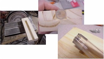 Within the next three steps, the overall length of the wood frame was trimmed to 9 1/2″, the tubing to 8″, the dowel to 8″, and a flat hardened flat washer was secured to the capped end of the tubing.
The length of the frame resulted from only what was necessary to match the tubing, plus 1 1/2″ for the cap. The frame was squared in a joiner and the face of the frame was cut to allow the tubing to rise 1/32″ above the face of the frame (center).
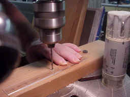 A rigid clear plastic ruler was cut down to 7 1/2″, about an inch more than maximum free length of a 1911 type spring. The ruler was double sided scale, so I cut the unused portion off and trimmed the ruler to a width of 1 1/2″ on the disk sander. I then drilled three mount holes holes, two ends and center.
The ruler was then secured to the frame and overlayed the tubing by 3/4″. The light pressure from the ruler on the tubing holds the tubing in place in the frame, and places the measurement marks directly over the spring coils when testing.
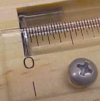 The ruler needs to be secured so it will zero in line with the surface of the flat steel washer, when the washer is under pressure from the recoil spring. The steel washer was used to prevent the recoil spring coils from damaging the wood, moving the zero point and causing inaccurate readings.
After a quick review of installed length and compressed dimensions of teh spring, I cut everything down just a little further.
Frame = L 9 1/2″ x W 2 1/2″ x D 1 1/4″
Tube and frame channel = 8″
Dowel 8″

This is the finished unit with recoil spring and dowel in place. Now all I needed was access to an inexpensive 50 lb postal scale to make the assembly useful. Not much to look at, but compared to a transducer pressure tester or a commercial spring tester, even with the cost of an accurate mechanical scale, I’m several hundred dollars ahead of the game.
How well did it work ?
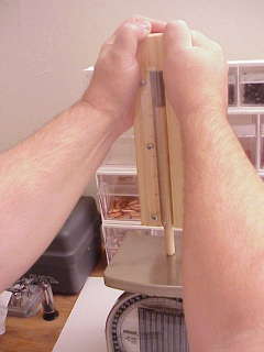 The chamfer on the end of the dowel and narrowed tip tend to force vertical alignment with the scale, improving accuracy of readings. In the beginning, I used calibration weights to verify and/or validate readings on both the mechanical scale and an electronic scale. Both yielded common readings within 1 or 2 ounces. When I started collecting readings, I cross checked results on both scales to verify virtually identical readings.
I took some time to research spring rates and reading methods for the 1911 design and came to the conclusion the intent was to have a 30 coil spring with a free length of 6.55″, that would coil bind at 1.375″ on .046″ wire. At full compression the spring would see 17.36 lbs.
I learned that mechanical parts tolerances and designed slide travel have a lot more to do with effective spring rate than the nominal ratings based on rate per inch, or compression to a theoretical length. In fact, the fully compressed rate of the same spring in two different guns could vary significantly.
Measurements and observations
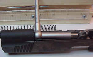 Potential coil bind: I used a telescoping gauge to check for the maximum installed length of the recoil spring. The actual measurement reflects the space that would be occupied by the recoil spring with the slide in battery position. Then I measured the maximum slide travel, subtracted that result from the first measurement, and determined the minimum space the gun would attempt to compress the spring into as the slide fully cycled pistol gun was fired.
Kimber = 3.650″/1.650″, Colt = 3.564″/1.464″
If you count a spring’s number of full coils, then multiply by the wire thickness, you’ll arrive at the coil bind dimension, or the point where all coils are touching and the spring becomes a piece of solid tubing. As an example, a 30 coil spring made of .046″ wire will become solid when compressed to 1.38″. While taking measurements as part of the spring tests, I found 6 of 12 springs tested would result in coil bind of some degree in a Colt Series 70, but all would have acceptable clearance in a Kimber.
I don’t think any of the binding distances were great enough to inhibit ejection or feed in the Colt, but I would assume the force of the solid spring battering the recoil plug, and the repeated shock and stress on the spring can’t be all good. Add a spring shock buffer to the guide rod, reach coil bind even sooner, and you could probably be shooting recoil spring plugs almost as fast as bullets. My only point is that recoil spring clearance is much closer than I had realized, and the use of heavy springs and buffers should not be done casually. If you have a gun that blows out plugs or buffers, you may want to check your gun’s compressed spring clearance.
| Spring Rating lbs @ full compression | 15 | 16 | 18.5 | 20 | 22 | 22v | 26 | 28 |
| Pistol Type | 1911 | 1911 | 1911 | 1911 | 1911 | 1911 | 1911 | 1911 |
| Spring Manufacturer | Colt | Wolff | Wolff | Wolff | Wolff | Wolff | Wolff | Wolff |
| # full coils | 31 | 32 | 32 | 32 | 32 | 31 | 29 | 30 |
| Free Length – uninstalled | 6.500 | 6.750 | 6.625 | 7.500 | 7.120 | 5.750 | 5.875 | 6.125 |
| Set Length – after cycling | 6.500 | 6.500 | 6.625 | 6.750 | 6.750 | 5.750 | 5.875 | 6.125 |
| Wire thickness | .0455 | .0460 | .0475 | .0480 | .0480 | .0470 | .0525 | .0530 |
| Installed length – slide closed | 3.564 | 3.564 | 3.564 | 3.564 | 3.564 | 3.564 | 3.564 | 3.564 |
| Compressed length – slide open | 1.460 | 1.460 | 1.460 | 1.460 | 1.460 | 1.460 | 1.460 | 1.460 |
| Coil Bind length – coils touching | 1.410 | 1.472 | 1.520 | 1.536 | 1.536 | 1.457 | 1.522 | 1.590 |
| Slide open coil clearance | .050 | -.012 | -.060 | -.076 | -.076 | .003 | -.062 | -.130 |
| Slide open coil clearance – Kimber | .240 | .178 | .130 | .114 | .114 | .193 | .128 | .060 |
| 6.00″ = force required lbs | 2.0 | 2.0 | 2.5 | 3.5 | 3.0 | – | – | 1.0 |
| 5.00″ = force required lbs | 5.0 | 5.0 | 6.5 | 7.0 | 7.0 | 3.5 | 4.5 | 7.5 |
| 4.00″ = force required lbs | 8.5 | 9.0 | 10.0 | 11.5 | 11.5 | 7.7 | 11.0 | 12.5 |
| 3.00″ = force required lbs | 12.0 | 13.0 | 13.5 | 15.5 | 16.0 | 11.5 | 17.5 | 19.0 |
| 2.00″ = force required lbs | 15.0 | 14.5 | 17.5 | 18.2 | 19.5 | 16.0 | 23.0 | 26.0 |
| 1.65″ = force required lbs | 18.0 | 17.0 | 18.0 | 20.0 | 22.0 | 20.5 | 26.0 | 28.0 |
| Variance to spring rating | +3.0 | 1 | -.5 | 0 | 0 | -1.5 | 0 | 0 |
| 15 lb spring was original Colt Gold Cup after 10,000 rounds | ||||||||
-
Spring free length is pretty much irrelevant. Installed length compresses all springs to the same uniform length and, hopefully uniform loading.
-
Regardless the starting length, the same rated spring ends up with the same rates, at the same stages of compression.
-
New springs taken out of the package that measure over 7 inches will take a set closer to 6 “, and remain there after being fully compressed once or twice.
-
Cycle a spring a half dozen times and it may lose 10% of it’s fully compressed resistance. Let it sit for 15 or 20 minutes and it will generally return to its full rating.
-
Life expectancy of a recoil spring. I have a standard Colt Gold Cup and another standard Colt, both exposed to over 10,000 rounds of ammo. The guns are loose, but the springs have held their correct free length and are above factory compression resistance ratings.
-
Some replacement Wolff springs come in at 1″+ under free length spec, particularly those in the extra power ranges. This to be meaningless in function and overall resistance.
-
Wolff does an incredible job of meeting and holding onto specs.
Quick Fixes – Fact or Fiction ?
Stretching springs to increase rates: I’ve frequently heard the suggestion that a problem with a too light recoil spring could be resolved by manually stretching the spring 20% to 25%. Compression spring rates are very much a product of wire diameter, material/temper, coil diameter, and number of coils. Minor stretching of a spring wouldn’t seem to accomplish much more than temporarily increasing the spring’s uncontained, or free, length. I’d guess that compression spring rates are based upon the accumulative result of torsional distortion of the spring’s individual coils, so any stretching that wouldn’t permanently alter the spring’s set would only have a temporary effect on the springs rate of resistance to compression. Don’t ask, I have no idea what the heck I just said.
In the following example I placed a spring in the test fixture and cycled it fully 10 times. After letting it relax for an hour, I checked the spring’s resistance at various points of compression. I then stretched the spring very carefully and uniformly by approximately 20% and checked compression resistance at the same points, then I cycled the spring fully 10 times again, allowed the spring to relax for another hour and checked resistance a final time.
| Free length | 6.75 | 8.10 | 6.75 |
| 6.0″ | 5.0 | 3.0 | 3.0 |
| 5.0″ | 9.5 | 7.0 | 7.0 |
| 4.0″ | 12.0 | 11.5 | 11.0 |
| 3.0″ | 16.5 | 15.5 | 15.0 |
| 2.0″ | 20.5 | 18.5 | 19.5 |
| 1.6″ | 22.5 | 21.5 | 22.0 |
The spring returned to its original free length but actually seemed to retain lower loadings at longer extensions, probably the result of permanent damage to the spring as a result of even modest stretching. These longer length rate reductions are pretty much irrelevant, because maximum extended length of the spring as installed in the gun would be approximately 3.6″.
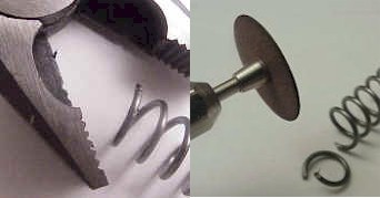
Spring Clipping and more significant stretching: Sometimes shooters clip coils in an attempt to reduce a spring’s resistance, or to increase coil clearance under full compression. Since I was going to basically destroy the spring, I thought I’d also go ahead and try stretching the spring to a point that I felt might permanently alter the spring’s set. Quick note on spring clipping – springs are hard, as can be seen by the paperweight, formally known as cheap cutting pliers. A Demel and a thin cut off disk is much faster, and much easier for trimming.
| Measurement | #1 | #2 | #3 | #4 | #5 | #6 | #7 |
| Free length | 5.7 | 5.5 | 5.2 | 6.2 | 7.0 | 5.5 | 5.3 |
| 5.0″ | 4.0 | 2.5 | 2.5 | 2.5 | 12.0 | 3.0 | 3.0 |
| 4.0″ | 10.5 | 9.0 | 9.0 | 9.0 | 15.5 | 9.0 | 9.0 |
| 3.0″ | 16.0 | 16.0 | 15.0 | 15.0 | 19.0 | 16.5 | 15.5 |
| 2.0″ | 22.5 | 22.5 | 22.0 | 22.0 | 24.5 | 22.0 | 22.0 |
| 1.6″ | 22.5 | 21.5 | 22.0 | 22.0 | 27.0 | 24.0 | 22.0 |
-
#1 readings from an new 22 lbs spring
-
#2 same spring with one full coil removed from the open coil end if spring
-
#3 same spring with two full coils removed from the open coil end if spring
-
#4 spring stretched to 6.2″, 19% above base
-
#5 spring stretched to 7.0″, 35% above base
-
#6 stretched spring after being cycled 10 times before checking
-
#7 stretched spring after being cycled 10 more times before checking
In general, for the price of a correct spring and the lack of results from stretching, clipping or maiming the spring in any number of ways, the best bet seems to buy the spring with a rating appropriate for the application.
Note on SIG Recoil Springs
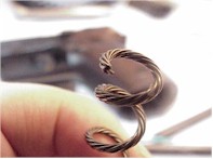 The first time I saw the Wolff replacement spring for the SIG, I thought I had an incorrect part. It has many more coils, much longer free length, and is a single wire versus the SIG’s 8 strand piano wire. Setting aside appearances, the Wolff replacement checked out appropriately and performed admirably.
I like the SIG recoil spring system much better than that used in the 1911 type. The spring has more working room, which should reduce the stress placed on this part, and there is no chance of coil bind.
| Spring Rating lbs @ full compression | 15 | 17 | 19 | 21 |
| Pistol Type | SIG | SIG | SIG | SIG |
| Spring Manufacturer | SIG | Wolff | Wolff | Wolff |
| # full coils | 10 | 17 | 17 | 17 |
| Free Length – uninstalled | 4.400 | 5.150 | 5.200 | 5.000 |
| Set Length – after cycling | 4.400 | 4.250 | 4.20 | 4.125 |
| Wire thickness | .0680 | .0430 | .0440 | .0455 |
| Installed length – slide closed | 2.750 | 2.750 | 2.750 | 2.750 |
| Compressed length – slide open | 1.460 | 1.460 | 1.460 | 1.460 |
| Coil Bind length – coils touching | 0.680 | 0.731 | 0.748 | 0.774 |
| Slide open coil clearance | 1.248 | 1.197 | 1.180 | 1.154 |
| 4.00″ = force required lbs | 2.0 | 6.5 | 5.0 | 1.0 |
| 3.00″ = force required lbs | 6.0 | 11.0 | 11.0 | 7.5 |
| 2.00″ = force required lbs | 9.5 | 15.0 | 15.5 | 13.0 |
| 1.00″ = force required lbs | 13.5 | 17.0 | 17.0 | 20.0 |
| 0.875″ = force required lbs | 15.0 | 17.5 | 18.5 | 21.0 |
| Variance to spring rating | 0 | +.5 | -.5 | 0 |
It’s extremely easy to change the recoil spring in the SIG P229, but a little more work for the overall project. All extra power springs also require the replacement of the inertial firing pin spring with one of higher rating. Unlike the 1911 types, the P229 needs to have a pin tapped out of the slide to gain access to the spring. Not a big deal, but another step. Just remember the left side of the frame is serrated to hold the pin, so you tap out left to right.
If you’re a shooter using a P229 shipped as a .40 S&W, but with a .357 SIG accessory barrel, you’re under sprung by a couple of pounds as the gun is received from the factory. Coupled with a light alloy frame, a heavier spring is a wise and inexpensive investment. I’ve been using a 19 lb spring for both .40 S&W and .357 cartridges and have had no functional problems with the pistol.
Closing Comments
I don’t think the tester will replace lab inspection equipment, but it is really helpful when analyzing changes. Sometimes in the process of working on a project, areas come to light that might have gone unnoticed. The issue of spring binding as an example, is a legitimate area of concern.
I suppose the gauge could have been pull through as easily as push, perhaps offering an easier and more routinely accurate measurement. As an example, known weights could be suspended from a pull line to check the degree of spring compression. If you make one like mine, make sure you add a hardened washer to the contact end of the dowel. The open coil at the end of the spring can make short work of bare wood.
Spell checks. When I write, I just sort of hammer away with a couple of fingers until pretty much everything is on the page. Then I usually go back and spell check, see what variety of English I’ve invented for the moment, and correct as much as possible. If I try to clean things up while I’m making a first pass, I lose my place, train of thought, and… I apologize for last week’s commentary, it was up for a week before it made it to the spell checker, and it was really bda.
Quick Notes:
Tiz Pozzobon has advanced engraving progress on his .600 double rifle project. After 700 hours, it’s beginning to carry as much gray scale and detail as photo art. Absolutely incredible work.
Doyal Wright’s Oregon gunstock blanks has a great site for people who like real wood. 7 types of walnut, plus fancy maple and myrtlewood.
Thanks
Joe

Email Notification