
Sometimes, working a firearm project is like being Marlow in Joseph Conrad’s Heart of Darkness; it is just one long trip up the river with surprises at every turn. What follows is my Astra NC-6 project diary. Let’s hope it comes to a better ending than Kurtz.
In the beginning…
There are lots of reasons to buy and shoot handguns sourced from military and agency surplus. The first reason might be their low cost. There are lots of handguns that have stood the test of time and combat/law enforcement worthiness that have been removed from active service and made available to the civilian market at a fraction of their original cost. How small of a fraction? A good .38 Special, manufactured in the image of a S&W K medium frame revolver, can be had for less than one hundred fifty dollars. One chambered in .357 Magnum for not much more. The attraction these low cost firearms hold for me is their often classic or unique and interesting designs, and their usefulness when learning how to modify, refurbish or repair firearms. It is a lot easier to work and learn when not under the pressure making a mistake and and turning an expensive firearm into a table lamp.
The revolver pictured above…yes, one of those things where the bullets go around, is typical of what is available through surplus resale channels. It is a Spanish made Astra NC-6 double action revolver with a 4″ barrel and adjustable sights. The example pictured above cost $139 and was condition listed as “Good”.

As received, bluing coverage was approximately 90% with expected holster wear at the muzzle and on the cylinder. There was a light bolt drag line over the cylinder indexing notches. The poly coated checkered grips were pretty clean, with the exception of the “beaver chew” at the top of the left grip panel. Screw head slots were relatively intact and even the importer’s stamp that is required by federal law was acceptably done. The bore was bright and rifling sharp. There were no signs of barrel bulges or general abuse and when I pulled the trigger, a stream of water didn’t come out of the barrel.
I think people who have an affinity for these types of firearms know the reality of a gun’s condition, but mostly see the future. It’s like being a kid and working on an old beater car. You know it has a broken window regulator, you know the trunk is rusted out. You know the blue smoke belching out of the exhaust pipe can’t be a good sign and you may even be wondering exactly what variety of animal ate the passenger seat. But one day, some day, the body will be straight, the interior will be restored and a 700 HP stroker will replace the death rattling six. It just takes a little work.
Welcome aboard the good ship “Anxiety”…
In my experience…and level of competence, double action revolvers aren’t as easy to work with as autoloaders. My relationship with revolvers is a lot like my relationship with dogs; I like them, it’s just that they keep biting me. I do lots of autoloader build ups. The projects usually consist of filling up a shopping cart at Brownells with drop in parts, doing some modest finesse parts fitting while following instructions, then heading out to the range where I always end up with an excellent, accurate and reliable shooter. In the majority of the cases, it’s the project gun I brought with me. Most people don’t realize that revolver parts are made out of elastic bands, each piece hand fit and assembled by highly skilled Bavarian elves working inside of a hollow tree. The revolver’s assemblies rotate and ratchet, push and shove, rise and fall and not always for an apparent reason. The rumor is that revolvers respond well to careful fitting and adjusting and care exercised in assembly. A brave new world, at least for me.
Necessary prep – I made sure the gun was empty, did this again, and made sure there was no loaded ammo near the bench and that no one else would have work area access. Some ops checks require handling a revolver in a manner that would, in other circumstances, be considered unsafe. At those times, being overly cautious is a good thing.
I was hoping the instruction were packed inside the box…
The first obstacle to overcome was figuring out how to get inside of the Astra, without doing damage, as there was no obvious barrel bushing or slide stop to remove. There were no NC-6 specific manuals available, but I did locate a source for a schematic CD. The CD did not provide assembly/disassembly instructions, but it did provide proper parts nomenclature in the event I needed to search for replacements and it did show the association of those parts. Looking at disassembly instructions for similar revolvers gave me some clues and I found the Astra came apart very much like a 4 screw Smith & Wesson…or almost every other revolver on the face of the earth with a side plate.
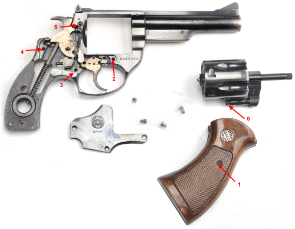
The screws that in one way or another secure the side plate are numbered respectively. #1 needs to be removed because the grips obscure #4. #2 secures the crane, which is labeled #6. They are taped to the paper because each is a little different and this is how I keep parts in their relative positions until I know enough about them to handle them more irresponsibly. Side plates are easy to chew up along the edges, so I got under this one at the mainspring, levering lightly above the hammer strut with a nylon pick. I lifted the plate a hair, then shifted over and did the same above the trigger, then back to the hammer strut location and repeated, with patience, until is lifted off almost parallel to the frame.
Next, the newly acquired Astra was given a bath. Sometimes the tight feel and close tolerances found in a used gun are the result of internal rust, grime and liberal doses of grease holding all of the parts together. Cleaning a gun thoroughly makes check out a whole lot easier and the resulting measurements and assessments more accurate. I used foil baking tins swiped from my wife to hold all of the parts and to keep the surrounding area clean, Gun Scrubber high pressure solvent spray from Brownells to clean all of the now exposed parts and a can of compressed air from the local discount stationary supply store to blow the parts dry. After cleaning and drying, I applied a couple of drops of Break Free on action contact points and went on to clean up and inspect the cylinder and crane assembly.
You say yoke and I say crane.
You live in Scotland, I live in Maine…
 I apologize for the musical moment. Sometimes it just gets away from me. As noted previously, the Astra is a S&W clone and, like the S&W, the cylinder/crane is disassembled in the numerical order appearing in the photo, right. The cylinder is held fixed while the left hand threaded extractor rod is twisted clockwise to loosen. The extractor will not turn as it is keyway locked to a tab in the center hole of the cylinder. The extractor rod is too tight for finger loosening, but it only requires a little more effort to pop loose. I put a piece of leather strap around the knurled rod end to protect its finish and gave it a light twist with a pair of pliers. With the extractor rod removed, everything else followed…or fell out.
Broken down to piece parts, a little more cleaning could be done and it was easier to check for excessive internal parts wear. It was also possible to measure the difference between the OD of the crane and the cylinder ID to see how clearance would contributes to cylinder slop in the reassembled gun. The shaft measured 0.3935″, the cylinder measured 0.3950″.
The measurements were uniform along the crane’s bearing surfaces and within the cylinder’s bore. Measurements taken at 90° increments about the perimeter, were essentially the same so nothing had worn egg shaped. There were no bright spots or obvious wear marks, which suggested the gun left the factory with pretty much the same dimensions. That was a good sign as repairing wobble and side play would require significant work or require the purchase of a donor parts gun.
The cylinder/crane was reassembled with a drop of Blue Loctite on the extractor rod threads, then the entire gun was reassembled. A spin of the cylinder and a couple of trigger pulls suggested at least most of the parts ended up in their original locations. Functional checkout continued.
The crane looks fine. Really. Just squint your eyes a little…
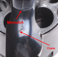
The fit of the crane to the frame was tight. There was no noticeable separation caused by the gun being mishandled, like from a one handed cylinder close flipping, or from shooting almost any of my handloads. The mismatched radius is a sign of two parts being finished as two separate processes. It is an aesthetic issue, not a functional issue as the lines that reflect bore/chamber center lines are straight.
With light drag on the cylinder, the gun was slowly single and double action cocked to see if the cylinder would index to approximately the correct position. It did. With the cylinder unlatched and spun, no tight spots were found that would suggest the crane was bowed. With the hammer down and the trigger pulled all the way back the cylinder could not be rotated in either direction, no rotational slop. Neat!
If I only could find a more complicated and unwieldy way…
I had measured and jotted down a bunch of numbers from the cylinder crane assembly, but I wasn’t sure what they would mean in functional terms when the cylinder was reinstalled in the gun. Was 0.0015″ crane/cylinder clearance good or bad? I had no documented point of reference. I knew a single action base pin could have that much clearance or less and thought to be good, but that had little to do with a system under load in a double action revolver. So I put together a Rube Goldberg fixture with a dial indicator that would read cylinder movement while it was part of a firearm assembly and began checking. Sometimes I do things like this because they help me to understand how things work. Once I understand how things work, I make far fewer misjudgments and truly spectacular mistakes.
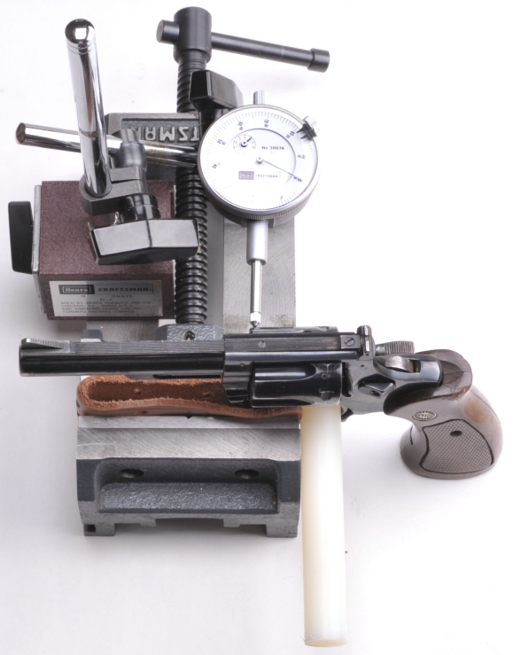
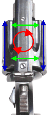 The dial indicator tip was placed at the leading edge of the cylinder, the cylinder was rotated off of its longitudinal axis by pushing first right on the aft portion of the cylinder while pushing left on the forward portion, then reversing pressure and pushing left on the aft section and right on the forward portion. The total sweep movement was 0.003″. I removed the gun from the fixture, rotated the cylinder 90° and got another 0.003″ reading. Checking for wobble – Red.
I moved the indicator to the mid point of the cylinder, pushed and pulled side to side with uniform pressure applied to the front and rear side of the cylinder to keep the cylinder parallel to the frame and got a reading of < 0.002″. Rotating the cylinder 90° gave me the same results. I took a peek at the extractor rod while I was wiggling the cylinder and it remained motionless. A look at the extractor at the recoil shield showed the same, no movement. So the small amount of cylinder slack was coming from the clearance between the crane and the cylinder. Checking for side play – Green.
Hammer back, trigger held depressed, there was no perceptible end shake. This step took a bit of care because it is easy to get wobbles and endshake mixed up. To check endshake the cylinder needs to be pushed fore and aft with uniform pressure applied to opposing sides of the cylinder. Checking end shake- Blue.
I decided to measure the diameter of the forcing cone at the read of the barrel, the funnel shaped over bore diameter opening that is intended to guide the bullet when it makes the leap from the cylinder to the barrel. Typical forcing cone entry diameters for the .38 Special and .357 Magnum with a .357″ jacketed bullet are 0.371″ min 0.378″ max. The NC-6 measured approximately 0.380″ or 0.023″ greater than bullet diameter. If the gun’s timing was OK, and as long as the wobble and side play were not the result of broken or worn out parts, that amount of play should be acceptable from a safety standpoint. Not that I was obsessing over this issue but… I also put two newer and demonstrably accurate revolvers on the same dial indicator setup and the movement at the cylinders was greater on both guns. I signed off on the Astra’s wiggle, wobble and endshake.
Headspace
Headspace is the distance between the rear sights of a revolver and the center of the shooter’s forehead. 38 Specials can work at 26″ – 34″, depending on the sleeve length of the shooter. A .460 S&W or .500 S&W level cartridge requires a distance several feet longer. Shooters with shorter arms can accomplish this with wrist extenders. Really. The best way to check a revolver’s more traditional headspace is to insert a headspace gauge in one of the gun’s chambers, rotate the chamber to alignment with the firing pin, then measure the space between the gun’s breech face and the headspace gauge with a feeler gauge. The procedure is repeated for all chambers. Headspace gauges are available from Brownells at an approximate cost of $30. They are useful when tracking a favorite and often used firearm’s condition and they are useful when checking out a used firearm before purchase. In my case, unlike Congress, I have to live within a budget. Appropriately, I buy gauges for popular cartridges and find other methods of measurement for those I handle less frequently.
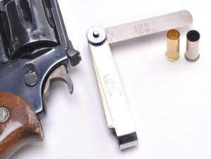 Most home shop gunsmithing reference books will suggest, as an alternative, using an empty and deprimed cartridge case in place of the headspace gauge. The procedure for taking a measurement remains essentially the same, but any gap measuring greater than 0.008″ would be an indication of excessive headspace. The problem with this approach are the large rim thickness variances that can be found within a population of mixed commercial brass.
The SAAMI spec for case rim thickness is 0.059 +0/-0.011 which means cartridges cases aren’t much of a checking standard. Depending on the brass selected, an 0.008″ gap between an inserted case head and the gun’s breech face could reflect headspace of 0.056″ – 0.067″. The SAAMI chamber drawing for the .38 Special, indicates a cylinder to breech face, min/max headspace to be 0.60″ – 0.074″. Using the Starline brass with a rim thickness 0.056″, the Astra allowed insertion of a 0.008″ feeler gauge blade between the case head and breech face which meant headspace was a measured 0.064″, or well on the tight side of the allowable range. If I had followed the general rule of thumb and did not take into consideration the SAAMI standard and the case rim thickness, insertion of an 0.008″ feeler gauge would have been interpreted as marginal headspace; in spec, but on the loose side.
Stop Gaps, shopping at the Gap and Cylinder Gap…
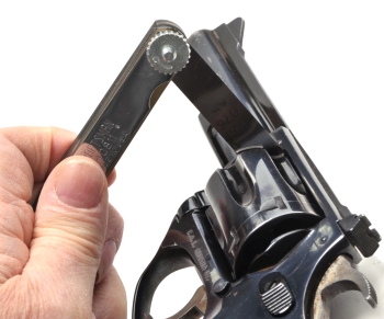 With the empty case and feeler gauge used to determine headspace still in place, the front cylinder gap, or the gap between the cylinder and barrel is measured. These facing surfaces need to be free of any residue build up to get an accurate measurement.
The NC-6 cylinder gap measured 0.004″, which is OK for guns that will see primarily jacketed bullets. I’ve seen 0.005″ – 0.010″ suggested as being OK, but when I find a gun over 0.006″ I usually start looking for whatever I need to do to close the gap down. 0.003″ – 0.006″ probably works for most people. 0.008″ might be a better number for folks who shoot a lot of cast bullets.
Cylinder gap represents a trade off. Increased space means a loss of gas pressure, velocity and possibly accuracy. Decreased space means a chance of gunpowder and/or lead residue between the cylinder and barrel preventing cylinder rotation. If you are like me, older than coal and not always in a hurry to rush off in six different directions, I find keeping a gun clean is a show of respect for machinery and it pays off with a bit more firearm performance. If you live life as though you are experiencing a perpetual sugar rush, or you compete in a venue that requires a lot of cast bullet shooting, opening up the cylinder gap is reasonable.
Odds and ends…
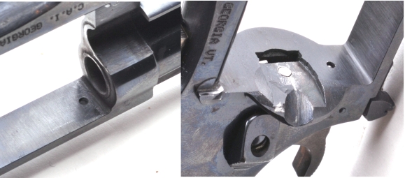
The gun has some very minor surface pitting that should come out with light polishing. There was no sign of gas cutting at the front of the top strap or the frame surface below. The recoil shield was in good shape in terms of surface wear and tear as well as firing pin and cylinder latch pin holes. Firing the gun with a sheet of white paper next to the cylinder with a 158 grain soft cast bullet load resulted in a narrow band of powder residue and the two or three near microscopic pieces of lead. Not bad. My guess is that the gun was carried a lot, but shot little.
And then the project actually got underway…
|
Astra NC-6 |
|
| Caliber | 38 Special |
| Capacity | 6 |
| Frame & Cylinder | Carbon Steel |
| Action | Double/Single Action |
| Empty weight | 25 Ounces |
| Sights | Adjustable |
| Barrel Length | 4″ |
| Trigger Pull Double Action | 9 lbs 11 Ounces |
| Trigger Pull Single Action | 3 Lbs 2 Ounces |
| Cylinder Gap | 0.004″ |
| Headspace | 0.064″ |
I almost knew what an Astra NC-6 was…well, not really. I knew it was like an Astra 960, but with a trigger guard like a Cadix, but the frame form and capacity didn’t track to either. I assume it is a popular law enforcement version of an Astra revolver that has covered the Western European landscape since the 60’s? 70’s? and has been present in surplus channels for some time. I did know how it shot, I knew its general condition and construction.
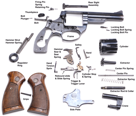
The nice part about working on an unfamiliar firearm is discovering all of its little design nuances. As an example, I wondered why the Astra used a regulation ring at the end of its hammer spring/hammer strut assembly instead of just using a web cast or machined into the grip frame. As soon as I removed the part and realized it has four cross location holes, each hole recessed to a different depth, I realized the ring could be rotated to regulate hammer spring preload. The nomenclature “regulation ring” made a lot more sense. Duh.
Where did all of these parts come from?
A photo is certainly not an assembly drawing, but I thought the factory nomenclature might be helpful for someone parts chasing for a rebuild. If this is too small a attached a larger version of the same.
Disassembly went something like this…
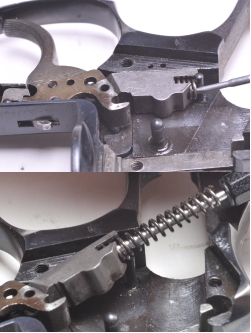
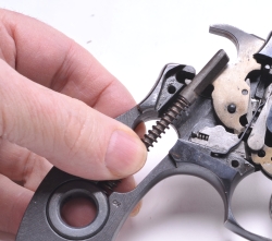 With the gun’s hammer lowered to minimize preload, the strut is held onto tightly and eased out from under the hammer and out of the regulator ring. It’s a good idea to mark the original hole location for the strut as each hole is recessed differently and yields a different load on the hammer and subsequent trigger pull. The rest of the assembly is still secured under spring pressure so the rest of the parts won’t fall out while you’re removing the hammer strut. With the gun’s hammer lowered to minimize preload, the strut is held onto tightly and eased out from under the hammer and out of the regulator ring. It’s a good idea to mark the original hole location for the strut as each hole is recessed differently and yields a different load on the hammer and subsequent trigger pull. The rest of the assembly is still secured under spring pressure so the rest of the parts won’t fall out while you’re removing the hammer strut. |
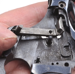
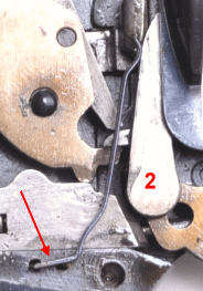 The next parts removed are the torsion spring, arrow, and the hand, 2. The arrow indicates the position of the two prongs at the base of the torsion spring that locate it to the spring. Grabbing there with a small pair of needle nose pliers and giving them a light tug is all that is required for removal. The hand, which will then be not under spring load, is swung counter clockwise on its pin axis, approximately under the “2”, and pulls straight out with light finger pressure. The next parts removed are the torsion spring, arrow, and the hand, 2. The arrow indicates the position of the two prongs at the base of the torsion spring that locate it to the spring. Grabbing there with a small pair of needle nose pliers and giving them a light tug is all that is required for removal. The hand, which will then be not under spring load, is swung counter clockwise on its pin axis, approximately under the “2”, and pulls straight out with light finger pressure. |
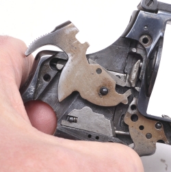 The cylinder release thumbpiece is depressed…no, not as an emotional state, just moved as through releasing the cylinder, then hammer is pulled all the way back. The trigger is also pulled all the way back or it will obstruct removal of the hammer. With hammer and trigger back the hammer will pull straight out. The sear and sear spring are press fit pinned and place so these parts should all come out as a complete assembly. The cylinder release thumbpiece is depressed…no, not as an emotional state, just moved as through releasing the cylinder, then hammer is pulled all the way back. The trigger is also pulled all the way back or it will obstruct removal of the hammer. With hammer and trigger back the hammer will pull straight out. The sear and sear spring are press fit pinned and place so these parts should all come out as a complete assembly. |
|
|
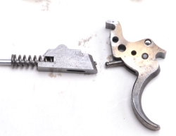 With the rebound slide out of the way, the trigger will lift right out. The trigger lever is pinned to the trigger and will remain in place…should remain in place. With the rebound slide out of the way, the trigger will lift right out. The trigger lever is pinned to the trigger and will remain in place…should remain in place. |
|
|
|
|
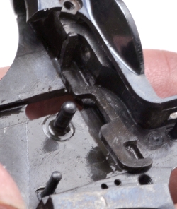 The safety is the next part to come out. It isn’t a traditional safety, but rather gets its name from the job it does in isolating the hammer from the floating firing pin when it is appropriate in the operation of the firearm. Nothing special here, it just lifts up and out. The safety is the next part to come out. It isn’t a traditional safety, but rather gets its name from the job it does in isolating the hammer from the floating firing pin when it is appropriate in the operation of the firearm. Nothing special here, it just lifts up and out. |
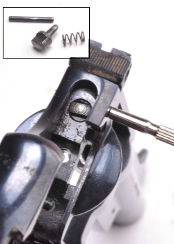 The firing pin and firing pin are held in the frame, surprisingly enough, by the firing pin retaining pin. The only problem I encountered was finding a punch small enough to clear the hole without doing damage. I run out of straight shank punches at 1/16″ or 0.062 and the hole size is 0.055″…0r 1.41mm as they say in metric land. I just ground flat and polished the tip off of a pointed punch to start the pin on its way out, then used a straight shank micro driver to push it clear. No damaged pins, no oversized hole. Neat. The firing pin and firing pin are held in the frame, surprisingly enough, by the firing pin retaining pin. The only problem I encountered was finding a punch small enough to clear the hole without doing damage. I run out of straight shank punches at 1/16″ or 0.062 and the hole size is 0.055″…0r 1.41mm as they say in metric land. I just ground flat and polished the tip off of a pointed punch to start the pin on its way out, then used a straight shank micro driver to push it clear. No damaged pins, no oversized hole. Neat. |
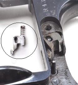
 The locking bolt, locking bolt spring and pin are arranged much like the firing pin assembly, only with a larger pin that will come out just fine with a 1/16″ punch. I have a #565 Brownells polished pin punch set that get a work out almost every day and the set is sized to accommodate most bench work of this type. They aren’t expensive and they are tempered to not bend at the first smack as I have experiences with most of the imported sets. Saving a buck is not beneath me, it’s just knowing where to save and what it will mean at the bench. The locking bolt, locking bolt spring and pin are arranged much like the firing pin assembly, only with a larger pin that will come out just fine with a 1/16″ punch. I have a #565 Brownells polished pin punch set that get a work out almost every day and the set is sized to accommodate most bench work of this type. They aren’t expensive and they are tempered to not bend at the first smack as I have experiences with most of the imported sets. Saving a buck is not beneath me, it’s just knowing where to save and what it will mean at the bench. |
 The rear sight is located in the channel on the top of the frame, secured with one forward screw. The aft screw is elevation adjustment. The thing I noticed about the gun was that a little solvent spray wasn’t enough to get the crud out of most places. Even under the sight looked like a bird feeder with all sorts of non-specific organic material. The rear sight is located in the channel on the top of the frame, secured with one forward screw. The aft screw is elevation adjustment. The thing I noticed about the gun was that a little solvent spray wasn’t enough to get the crud out of most places. Even under the sight looked like a bird feeder with all sorts of non-specific organic material. |
Concluding Part I …
|
When I wrapped up this part, I had a used firearm that was basically sound and every small piece part or assembly was stowed in individually labeled plastic zip locks. The plan is to strip the Astra, clean, polish and refinish it, tighten up the its timing, treat it to a trigger job including a set of more appropriate springs, upgrade the sight system and, time permitting, fit it for a set of nifty grips. Next time. |
One Man’s Surplus is Another Man’s Project Gun… Part I
One Man’s Surplus is Another Man’s Project Gun… Part II

Email Notification