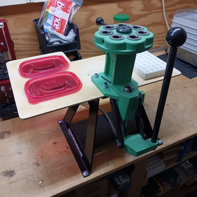
03/12/2023 – When the original reloading press tray 1.0 was constructed, above, there was no intention to rest on our laurels. More so, we were surprised, after extensive research, that laurels was not a metaphor for “butt”. The process goes something like this. Get an idea, turn it into something rough but tangible, work with it to sort the good points from the bad, refine the design.
In general, it was handy in the way it elevated materials to work level. Negatives? The board was too flimsy, the material trays needed to be pulled forward, notching the back was a waste because that yielded no useful work space below and surrendered work surface. The tray surface could be better utilized.
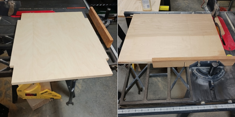
Based on using the original tray, the board was increased in size to 22″W x 17″D X 1″ thick. An oversize piece was found in the scrap box, birch face plywood cabinet grade, squared up, cleaned up and cut to 22″W x 17″D.
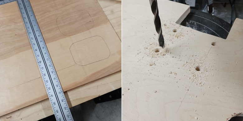
There was no reason to locate the bins so far back and there was no reason to have the leading edge of the tray so far back. So the first bin was relocated 3″ back with a 2″ space between it and the second bin.
A 3″D x 4″W cutout was made at front of the tray to allow the rest to be brought forward with clearance for the press linkage and primer feed. The press mount studs are 5/16-24, but this time I drilled the tray with 1 3/8″ brad point drill for easier assembly.
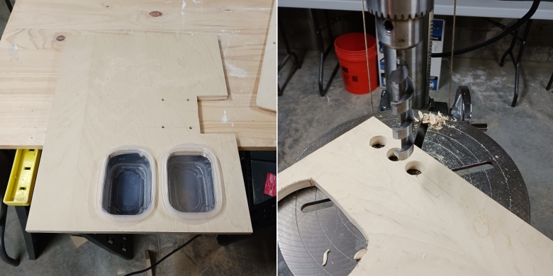
Hardwood plywood is tough, so a hole saw provided an insertion point for a saber saw. Functionally, the openings worked to secure the bins. Workmanship? A “C” at best from Mr. Whiting. Next time I will make a better template and finish the holes with a router.
A 1″ boring bit was used to put three die stowing holes at the back of the tray. They are not intended to hold die sets, only the dies that move off and onto the press during a loading session. As an example, I size first and then prime. I do not leave the sizer die on the turret head as a safety precaution. I am too lazy to pull the decapping pin. Sometimes it’s a bullet sizing die or a unique crimping step. For now, three holes are a starting point.
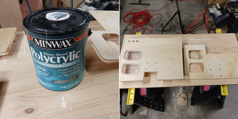
The applied finish is clear and makes for a good surface for finding things. I found that it takes one lap around the lid with a screw driver for every year of finish age. This took 10 and, no, fresh is not required, just a tight lid seal. Side by side, new to old.
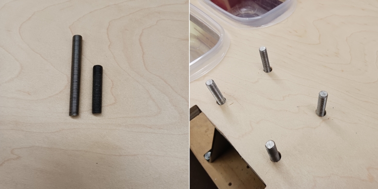
The tray thickness increased and there are plans for mounting other gadgetry at a latter date, so the 5/16-24 studs were increased from 1 1/2″ to 2 1/2″. Did not want to wait for threaded rod to arrive to fabricate studs, so these were picked up at Granger.
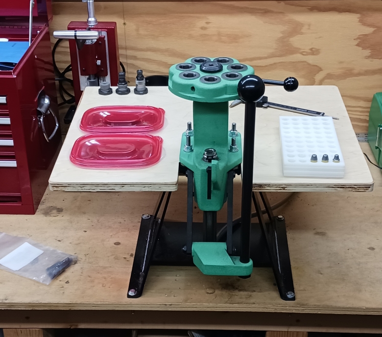
So this is the current 2.0 stable release and there is a 3.0 in alpha. Not sure if the back of the tray needs an edge. Not sure if more drill holes and hooks can put the constant use gadgets all on the tray or if that will create clutter.
The height and reach seem right as I can work at the bench for extended period without having a sore back. Maybe it needs pull draws on either side, under the tray. It is just enjoyable running some machines and making something. The project got me to finally slow the drill press down, change the paper on the vertical belt sander and swap the cross cut blade for the ripping blade on the table saw.

Nice refinement to a good idea. Is there a reason the holes for plastic contsiners are so far back from the front edge of the tray? Is that where your hand naturally goes to feed the brass and bullets to and from the press? With the added material thickness it would seem to be a wider tray boarder than is needed for strength.
Looking forward to 3.0.
Scott
Yes, Scott, they could be farther forward on the board and probably rotated 90° so they are side by side. There is a lot of space to stow accessories not i n constant use, or I may trim a couple of inches off the back. It is positioned in the front so it does not stick out beyond the bench so I don’t walk into it…
Joe