Being a self taught machinist is a lot like being a self taught neurosurgeon… except the patients, and/or their families, don’t complain nearly as much. When I tackled the issue of turning speed, I read the books that indicated material type, diameter and type of operation should all be considered before reaching a conclusion. Unfortunately, most of my turning stock inventory usually begins life as a piece of scrap metal or, occasionally, a piece from the tractor… or my wife’s truck. The best I could do is determine plastic, aluminum or steel, which gets me no place on the great matrix of material, size and speed.
Generally I use the spin and burn technique of lathe speed selecting; crank up the lathe until the cutting tool burst into flames, then back off one pulley position before proceeding. Tool life isn’t great, but it is truly a spectacular process to watch. There are operations, however, that require very slow speeds to the extent I run out of pulleys before I run out of speed.
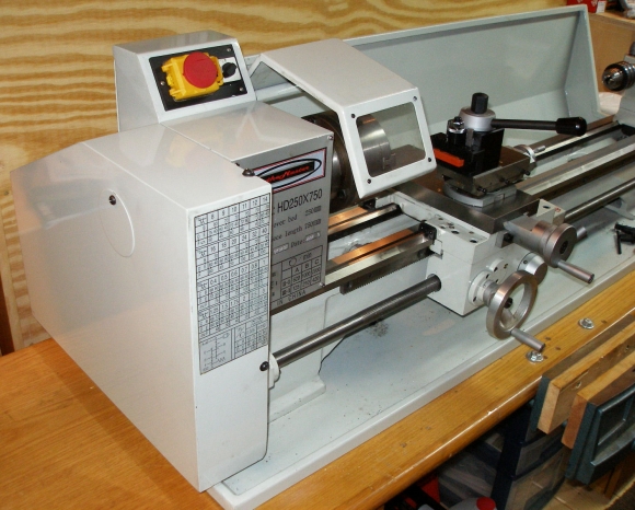
LatheMaster offers a way to extend the low speed range of their 8×14 and 9×30 lathes, in the form of a $129 speed reduction pulley. A planetary gear drive causes the speeds to be cut in half while allowing the pulley sizes to remain the same, so the unit is a novice drop in and compatible with all other components of the lathe’s drive system. Rotation direction is reversed, however, so the the direction switch is set to reverse when the speed reducer is in use. Direct motor to spindle pulleys and speeds remain the same with the reducer installed.
Installation overview…

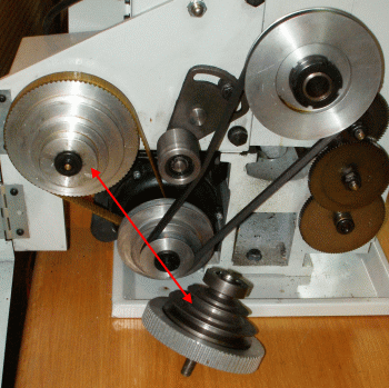
The new piece is shown on the bench with the original pulley set still on the lathe. The speed reduction planetary drive pulley set arrives complete with center shaft. Where the original pulley set is all aluminum, the speed reduction pulley has a toothed aluminum drive pully with steel V belt transfer pulleys. Only the nuts that secure the shaft to the lathe frame are carried over from old to new.
The original pulley set is secured to its center shaft with an E Clip. For the sake of illustration and visibility the pulleys were removed from the shaft. These two components do not have to be separated to make a pulley set change out. The LatheMaster 9×30 lathe is laid out well for set up and service.
Not in the least bit a complicated task…

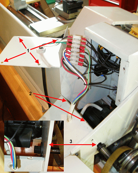
Before any work begins, especially because protective electrical covers are removed during the installation process, make sure the lathe is unplugged from its power source. Above – Step 1, the four electrical cover screws are removed. Step 2, the motor cover screws are removed and the cover is pulled back to expose the pulley shaft’s double retaining nuts on the inside of the lathe’s frame. Step 3, the pulley shaft is removed. Again, the pulley and shaft may be removed as one assembly. It was removed in this case to provide part visibility. Reassembly in a simple reverse of the process.

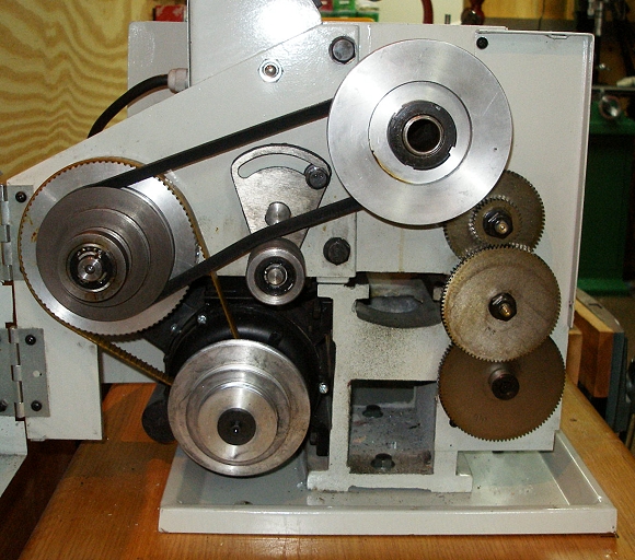
With the new pulley installed and the belt routed to use the newly available slower speeds, the drive side should look something like this. I’ve seen pictures of installation where the drive belt is routed under the central idler pulley, placing the narrow fact of the belt as the idler pulley contact surface. The belt should have its wide side in contact, over the top of the idler. When finished my installation the belt was too long to allow proper installation. It had just been stretched from use. A new Z737 belt allowed correct routing with virtually all idler pulley range of adjustment intact.
 With the speed reducing pulley in place, the three slowest speeds are cut in half, for low speed – high torque single point threading, grooving and parting operations. For more typical operations, the bent is run between the motor and spindle pulley sets for turning speeds in the 620 – 2000 RPM range, which remains unchanged.
Email Notification