 If I had my choice as to how I would spend my time, it would be building one off prototype firearms and cartridges. Which is a little ironic, as I am not actually skilled in any of the associated technical disciplines. Yet, here I am, a couple of decades since my first attempt, all fingers and toes and no sign reporting the number of days since the last occurrence of an industrial accident hanging in the shop. Patience, research and preparation are worthwhile investments.
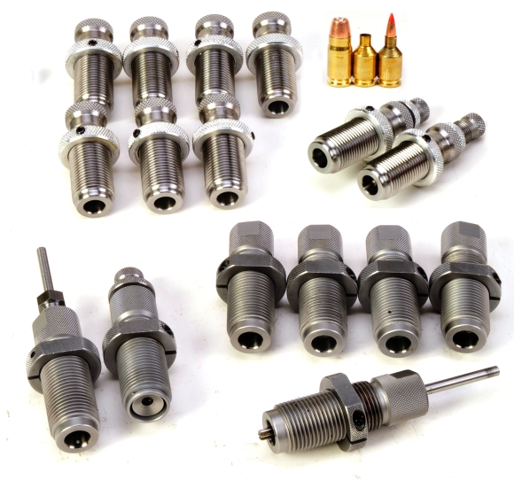
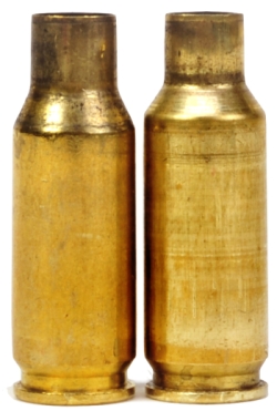 Other wildcats reflect more modest modification to a parent case and require only a single sizer die and single seater die to mechanically form a case, even though fire forming may be required to properly relocate case shoulders or to remove case taper. Even here the purchase price for custom dies typically runs $200 – $250 and the same extended lead time applies. An example of this type of cartridge is the .358-378 RG, which is made from .338-378 Weatherby or .378 Weatherby brass.
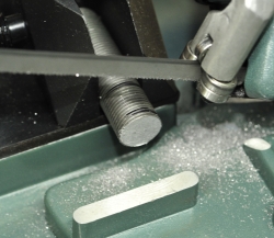
The chunk of cut threaded rod was clamped in the lathe’s chuck, critically marked with a felt tip pin to indicate the area planned as the clean die top, then de-threaded within an inch of its life. The thought was that even though threads on a cheap piece of threaded rod were probably not… precision, they were what was going to locate the die in the press’ die head and control press to cartridge case longitudinal alignment. A quick read with a dial indicator and a little check/stock wiggling actually removed most of the concentricity wobble and all of the cuts through the full die length pilot hole cut were done without removing the stock from the chuck to maintain alignment.

A sizer die is machined as a negative of the cartridge case at the bottom portion, and machined for an adjustable decapping rod/expander assembly at the top. The bottom would be cut on the lathe with a reamer slightly smaller than the chamber reamer, the die top would be machined and tapped with more generic tooling.
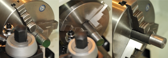
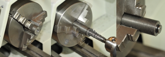
 As illustrated in the three frames above, beginning with a center drill, and incrementally increasing twist drill sizes, the die body was drilled through until a hole size of 0.277″ was achieved. The 0.277″ limit would me smaller than the neck cut area of the sizer reamer, but large enough to pilot the reamer in a future step.
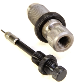 Subsequent drilling into the top of the die was limited to a depth of 1.075″, drill size was incremented through to 29/64″. This was done to accommodate a 1″ deep cut with a 1/2 x 20 NF tap. Using this standard allowed the choice of fabricating a decapping rod assembly or purchasing one as a spare part from Redding. Redding die and rod assembly pictured left illustrates a tapped die body and rod assembly.
Die length is important as it sets the timing of the sizing process; when the case neck and body are being reduced and where the expander is when this happens. Basically, the expander should enter the case and clear the neck before the neck is sized (reduced) by the die. The expander is then pulled into the neck after the case neck is no longer in the forming portion of the die. The sizer will form the case well under size, the expander will bring the neck ID back to a few thousandths under size. Just enough to provide bullet retaining tension, but not so much as to make bullet seating difficult.

The die was left in the lathe chuck when it was threaded with a manual tap. Pretty easy step. Over the years I’ve accumulated a lot of handy small tools. Long ago, Brown & Sharpe thimble read micrometers were the only brand a machinist would put in a tool box. Then it seemed Starrett was a good product… then Mitutoyo I’d guess, particularly with digital read mics.
I try to buy, besides what I can budget for, what is consistent with the work I do. If I am chopping away at a piece of steel that is +/- 0.500″, I hardly need a $600 micrometer when a $75 import will work. So I buy more costly tools only out of necessity, take good care of them and use them only when necessary.
A ranting interlude…
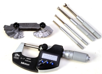 The money I save, by buying tools consistent with the dimensional tolerance requirements of my work, goes to purchasing lots of inexpensive handy tools that make life easy and allow me to attempt more complex projects. Owning a $7.95 Enco 4-84 screw pitch gage, rather than a $75 Starrett gage sold through Grainger, works for me. Owning a $8.95 small hole gage set rather than the $121 Starrett version of the same is even better. Owning a $135 coolant proof 0.00005″ digital micrometer from Enco is better than buying the same from Grainer for $197, especially on an Enco free shipping and %15 off day.
So why am I yammering about all of this in the middle of a die making piece of… literature? Because I wanted to make the point these are not expensive tools and they are good to accumulate because access expands the universe of firearm enthusiasts. I have no problem paying exorbitant prices for US made products, but only if the highly paid executives of those companies will sit down with me at the end of the month and bring along some checks to help me pay my bills.
Confessions of a reamer killer…
I finally had to remove the in-process die and flip it around in the chuck. The pilot hole was two stepped; 0.277″ was the pilot hole that was drilled from the other end of the die and intended to support the pilot bearing on the end of the sizer die reamer. I made a second shallow cut, maybe 0.250″ deep and 0.400″ in diameter to help ease the stress of the tailstock anchored reamer coming into alignment. I do not have a re-circulating coolant system on the lathe, so the lathe speed was reduced and heavy cutting fluid was periodically applied. This kept the reamer’s screams to a minimum and all material just slightly below critical mass and fusion.
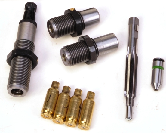
The depth of the cut was determined with a headspace gage that was ordered with the reamers, above, far right. The cut was made right to the top edge of the extractor groove with the expectation that sample sized cases made from the would determine the final dimension and this would be achieved by trimming and polishing the nose of the die.
Almost got it right… and then the Tribbles arrived
The first cases through the sizer were slick. The neck resize stopped at the right location, based on the where the shoulders would be after fire forming, and the machine work was clean enough to allow the sized case to be extracted with normal exertion – no hammer or stuck case remover required. Unfortunately, when I placed a bullet at the case mouth it fell through to the bottom. Head scratch, head scratch. The die was cut appropriately based on the reamer dimensions, but the problem originated with my original case drawings.
Material thickness used in cartridge brass differs so, for example, the material thickness of a 7mm-08 Remington can’t be used to determine the material thickness of a 30 Remington AR case or a resulting 7mm-30 RG case. Often SAAMI standard case drawing can’t be used to determine material thickness as these represent maximum dimensions. In the case of the 7mm-30 RG, I used the material thickness standard for the 30 Remington RG, which is the same as the 7mm-08 Remington, 0.016″ and the sizer reamer was cut 0.004″ under to provide proper neck tension on a sized case. Unfortunately, no Remington parent case measured thicker than 0.012″ for a difference of 0.006″ diameter so case necks were not being adequately sized. Quandary to follow.

The simple corrective action seemed to be to have the reamer ground further undersize to account for the thinner than expected brass, but then what would happen if a supply of brass ran closer to specification? I’d have to neck turn cases. Since the amount of reduction required was small, the decision was to make two forming dies, where either could be used as a secondary sizing step to accommodate variations is case material thickness. As no letter or number drill corresponded to the exact size needed, an “M” 0.295″ drill was used to rough out the hole size, then an adjustable hand reamer was used to finish the hole to the proper dimensions. In this case 0.303″ and 0.306″. Eventually, the reamer was ground undersize approximately 0.004″ which yielded a single sizing die solution with the secondary dies available if necessary. After this sizer die exercise, it was on to the seater die, which is covered in Part II.
Why? Why?… Why?
Gaining valuable experience? Developing firearm associated skills? Self satisfaction that comes with self reliance? A sense of exploration? Learning something new? One of the nicest parts of being a firearm enthusiast is that owning a gun is just a starting point.

Email Notification