
The pictured High Standard AR has been with me for a long time, serving as the shop’s AR 15 test mule. Its internals are excellent, it is an accurate and reliably functioning piece of equipment. Head space is good, upper and lower fit is tight and the bolt locks and unlocks when appropriate.
Externally, the rifle is seven shades of black and gray, it has a bad grip and incorrect sights, a tin can magazine and a top rail that leads nowhere. The mil spec trigger is long and gritty and pull is never the same twice. The rifle lives in the back of the safe and it goes to the range only when necessary and, even then, only when no one else is around. It is not suitable for many projects, as photographing a nice new part installed on this rifle is like hanging the Mona Lisa on an outhouse door.
Ultimately, honorable service warrants respect, so I thought it would only be right to dig around in the shop’s under counter boxes marked, “Miscellaneous AR parts” and see if Lucille could be cleaned up, reconfigured and used for more everyday practical assignments.
What is wrong as I see it?
The rifle is heavy at 9 lbs and long for an AR at 39″.
The pull length is not ideal in all shooting positions.
The sight set is not ideal for moving woodland targets.
The 223 Rem is not my idea of a deer and hog cartridge.
The barrel length is too long for a woodland rifle.
There is no need for a flash suppressor.
The grip feels like a giant soft eraser.
The magazine capacity is too high for Maine hunting.
The trigger is… shotgun like.
What’s the plan, Stan?
We are jammed up with work and heading into a very busy time of year with a full schedule, but there are too many of these types of projects around the shop to ignore. So the plan is to grab a few minutes when I can, work the projects one step at a time, and see what happens. We’ll post progress and the general steps taken to perform the work.
The thought is that these are simple steps and basic tasks, so putting them up in public will take away all excuses from other lazy people, with similar firearms, in similar condition and shame them to action. Much of the material comes from Brownells so, where possible, I’ll list stock or part numbers and current prices. Good people.
Is it a “carbine” or a “carbean”?
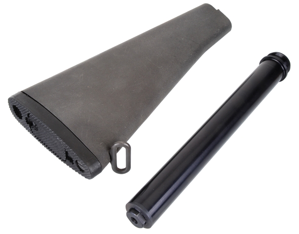
The thing is, if the rifle is going to get shorter, it has to happen at both ends, shorter stock and shorter barrel. The barrel end will have to wait for another day, but the stock can be changed out now.
Parts in the bench scrounge boxes were part of a High Standard carbine stock mounting kit, Brownells 080-000-624WB Commercial Buffer Tube Assembly $63.99. Included in the kit: Carbine recoil spring #430000509, Carbine 6 position extension tube (1.170″ diameter) #430000511, Carbine buffer assembly #430000510, Receiver plate #080000290, Carbine extension lock nut #430000532. The stock is a simple Magpul CTR commercial tube adjustable stock #100002982.
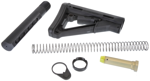
The spring is a typical 38 coil carbine type and the buffer weighs 2.9 ounces. This is good enough for a place to start, but the buffer selections will be refined when the firearm is completed and test fired. In the mean time, pulling the rifle buffer and spring and replacing them with the shorter carbine pieces should prevent damage to the lower assembly or extension and prevent the firearm from short stroking.
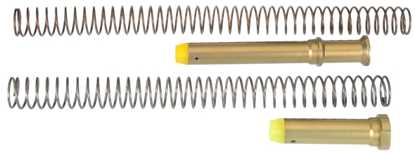
The rifle recoil spring, top, should have a maximum coil count at or near 43, the carbine recoil spring has a maximum of approximately 39 coils. The carbine spring is a couple of inches shorter. The rifle buffer is approximately 6″ long, the carbine buffer is approximately 3 1/4″ long.
Highlights of the change out
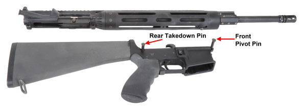
The magazine is pulled, the bolt is opened and the chamber is checked for empty. The rear takedown pin and front pivot pin are pressed to the out position and the upper assembly is separated from the lower assembly. I always wonder why the “rear” and “front” designations as there are no opposing counterparts. I always use one of a few plastic takedown tools to push out pins. I know it isn’t as manly as pulling them out with my teeth, but I like the idea of not having scratched up pins.

All of the work that follows was accomplished with the lower receiver sitting on a lower receiver vise block and held in a vice…. Unfortunately, the block made of white Nylon 6/6 and tough to photograph against a white background. Fortunately, the new Brownells #080-000-662WB Lower Receiver Vise Block is dark gray so you can use it AND photograph it quite easily. The point is that having the lower held in place like this keeps it upright and leaves both hands free to install parts.
The buffer is under load from the recoil spring. To remove, make sure the hammer is cocked, which will place it in a down position. If you are a careful type and know enough to ease the hammer up when the trigger is pulled to protect the lower receiver, move ahead. If there is a chance you’re not that considerate of mechanical things, insert a hammer drop block like Brownells #080-953-000WBAR-15 Hammer Drop Block $29.99 which will protect the lower from inadvertent hammer strikes and become very useful when trigger work is done.
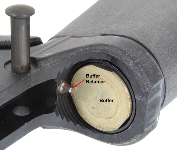
So the deal is to put a thumb on the buffer so it doesn’t play jack in the box when released, then depress the spring loaded buffer retainer with the other thumb and allow the buffer to ease forward under recoil spring power.
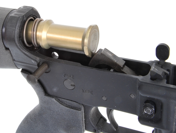
By retaining the buffer with one hand and pressing downward on the hammer with the other, the buffer and spring can be eased out and removed. The buffer and recoil spring provide appropriate resistance to the rearward traveling carrier assembly as it stores energy, then it drives forward to move the carrier assembly to battery while chambering a fresh round. Spring and buffer weights can be juggled to achieve optimal balance of compression and expansion.
If you have worked on AR type firearms, you know that they are all booby trapped, little springs and detents hide behind everything, waiting to jump out and hit you on your bozo nose or to shootout and disappear against your camo ceiling, walls or floor. There are two such booby traps to uncover when pulling a butt stock and extension tube.
With the lower sitting on a receiver block, the pressure is applied to the butt stock to keep it in place while the top fastener on the buttplate is unscrewed from the end of the extension tube. When the screw is free, an open hand can be placed under the union of stock and lower receiver while the stock is eased rearward and off of the tube. Bottom right shows the detent spring and takedown detent you want to recover from the takedown detent well bore in the lower receiver. With the buttstock removed, a Crescent wrench… or Croissant wrench as they say in France and several parts of Canada, is used to grab the flats at the end of the extension tube to break the tube’s grip on the lower receiver.
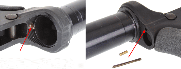
Bottom left is booby trap #2, the spring loaded buffer retainer which, in itself, being retained by the end of the extension tube… a little mechanical irony. In any event, a thumb over the buffer retainer as the extension tube is unscrewed from the lower receiver will prevent the buffer retainer from falling out and forever disappearing on the floor like socks in a clothes dryer.
Below, (1), the extension nut is screwed all the way onto the extension tube and the keyed receiver end plate is slipped over the extension tube threads and down to the extension tube nut. The takedown detent and detent spring are inserted into the detent well ad the extension tube assembly is screwed into the receiver threads until the tube traps the shoulder of the buffer retainer (2).
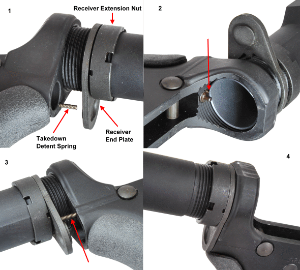
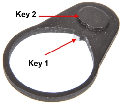 The receiver end plate is keyed to the extension tube, key 1 so that one cannot rotate without the other and there is a locating key 2 that locks into the rear of the lower receiver and prevents the extension tube from working backing out in use. The end plate also retains the takedown detent and detent spring.
After the extension tube is on position over the buffer retainer, #2 pic above, the tube is rotated just enough to position the end plate over the detent spring, and then it is pushed forward to push the spring into the well and to insert the lower key into the recess in the rear of the lower receiver. Then, as pictured in 4, the receiver extension nut is drawn up against the end plate.
Occasionally, the tab that locks to the extension tube, key 1) is oversized and needs to be hit with a file or stone so that the end plate drops over the tube threads without hanging up. I use a relic armorer’s wrench as pictured below, Brownells 080-001-208WB AR-15 Armorer’s Wrench and hand pressure to torque the extension nut.
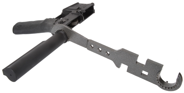
A little fancier stock tool that more easily facilitates torquing the extension nut is Brownells 080-000-291WB Buttstock Tool that comes with round and square spanner pins, an opening that fits rifle length extension tube nuts and a screwdriver to loosen butt plate screws. If a torque wrench is used, the torqued value should be 38 to 42 ft-lbs, but the torque needs to be adjusted to compensate for the distance from the torque wrench location in the spanner tool to the center of the extension tube nut to account for the extra leverage. As an example, if the desired torque was 40 ft-lbs, the torque wrench length was 15″ and the distance from the wrench hole in the spanner to the center of the nut was 3″, the torque wrench would be set a approximate 33 ft-lbs.
TS=TxL1/(L1+L2)
T= torque in lb.-ft.
TS= torque scale in lb.
L1= torque wrench frame length in inches
L2= torque wrench extension length in inches
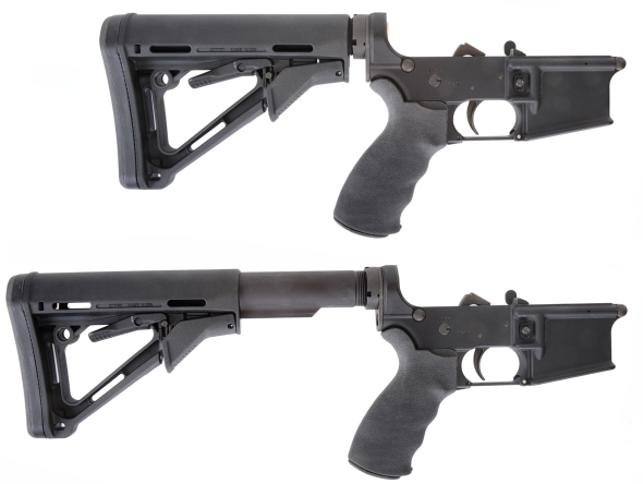
With the extension tube properly secured, the new short buffer and recoil spring are installed and the buttstock is slipped onto the extended tube and locked in place.

The combination of this extension tube and Magpul stock can be adjusted to any one of six locking positions or fully collapsed. Length of pull is 10.5″ – 14.25″.
With a few more minutes of free time left before getting back to real work, I thought a grip change could be squeezed in. This was also found in a box in an unopened blister pack in a box of AR parts.
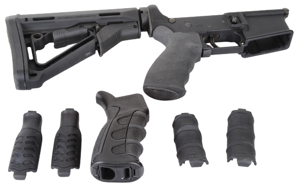
OK, no, this grip isn’t really ME. A few too many lines going in way too many directions and I am not sure if I will ever have a need to change the back straps or finger groove panels. Still, they are better than the sponge ball grip that was on the rifle, sooo… The grip is made by Command Arms. No longer sold through Brownells, it is still available on the manufacturer’s site.
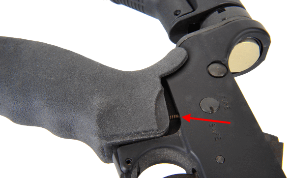
The grip swap is quick, with one central screw running up the center of the grip and into the frame. The only thing that needs a little care in handling is the selector detent and detent spring. The spring resides in a well in the top of the grip and once the grip is pulled down a bit, both the spring and detent are free to roam.
Many words and pictures for fifteen minutes worth of work…
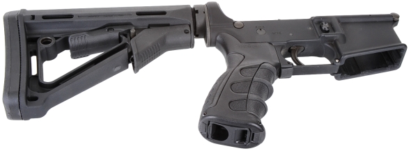
A long ways to go, but a bit of a start. For now, back to the real project work. Maybe we’ll take a run at the trigger next.

Email Notification