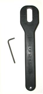
It is with the implements pictured left, I have mutilated, bent, spindled, and inappropriately folded quality scopes many, many…many times. It isn’t as though I’m unaware of other tools to use, and approaches to take when mounting scopes, it’s just that I tend to reject complex approaches to what I define as simple tasks. Unfortunately, my labeling of a task as simple, is sometimes based solely on my inability to fully grasp the substance of the situation. It just so happened that another project was causing me to play musical scopes, so I decided it might be a good time to look beyond my basic scope mounting resources; a scope ring wrench, a cheapo Torx® wrench and an apparently overrated eyeball – brain interdependency intended to properly align a scope to a firearm.
This isn’t a “How to” as much as a “So that’s what I should have been doing” article. I began with an examination of one of my “two tool” scope installations, checked for obvious errors and omissions, and thought through what I could do to improve my overall quality of the work in this area. In the process, I took a close look at the steps typically recommended to try to figure out what was important, why it was important, and what the benefits would be if I applied these steps to my own scope installations.
If it doesn’t kick it, it doesn’t matter….well, actually it does.
I think most people pay more attention to detail when they are mounting a scope on a rifle with heavy recoil. To a degree, this makes sense. Heavy optics take a beating from heavy recoiling rifles; the rifle is moving rearward, the scope wants to stay where it is, the rings need to provide insurmountable friction to retain the scope in position, then the mount system and hardware need to absorb the G force loading of the scope. In this regard, high power rifles present a challenge. On the other hand, simple improper tightening of hardware and improper alignment of bore, scope and earth’s horizon will make both a little .223 Remington and a .338-378 inaccurate and inconsistent in shot placement. So, it seems, both types of installations should be treated with equal care. I don’t include scoped handguns in this piece because I can’t hit with them even when the scope is right, with the exception of a T/C which is not really a handgun, but more of a really short rifle. Anyway…
The following information was gathered while removing, checking and reinstalling a scope on my .338-378 Weatherby, and I’ve noted some of the more specialized tools I used during this exercise. It is not a step by step set of instructions, just more of a highlight of the steps typically suggested, but not typically accomplished, at least not my me.
Scope Ring Alignment Rods
Rings and bases are typically held to an individual surface +/-.005″ dimensional tolerance, and there are lots of dimensioned surfaces; ring hole alignment, saddle height of rings, base height, lug height, radius under the base, etc. It would not be uncommon to find an accumulation of dimensional variances that add up to .015″~.025″ vertical or horizontal misalignment between ring centers. This misalignment poses at least two practical problems. Forcing a scope into misaligned rings could damage the internal mechanical and optical parts, plus the distortion could cause optical misalignment. Even a small error would be highly magnified down range. A .025″ downward distortion of a scope on 4″ ring spacing could shift bullet placement upward as much as 44″ at 100 yards. The scope’s external vertical adjustment might be able to compensate for the problem, however, 44″ of the scope’s adjustment range would be lost. A good installation would yield a 100 yard zero with scope adjustments at, or near, the mid adjustment range position.
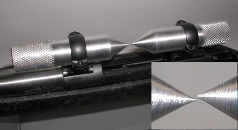
I removed the scope from the Weatherby, inserted a pair of Brownells‘ scope alignment rods and found, as illustrated in the inset photo, the points were inline down the longitudinal axis of the barrel, however, they were not parallel to the bore in the vertical axis; the point of the front rod was .010″ below the rear rod. As the rod points were approximately midway between rings, the actual offset across the entire distance between rings was closer to .020″, which would place the bullet 36″ higher at 100 yards than anticipated. In fact, the scope had been adjusted well into it’s range to zero.
The typical solution to this problem of vertical misalignment, is the installation of shims under the low base to bring the two bases into alignment. Shims are available, pre-punched and shaped for standard base hole spacing from companies like Brownells or MidwayUSA. Shims can cost as little as $3 per small assorted set, and up to $65 if you like to have those “just in case” part sets stacked up on your work bench. A less expensive alternative is to pick up shim stock at one the tenth the cost from an online machine shop supply company, along with an inexpensive shim punch set. Burris Signature Rings Pos-Align® Offset Inserts offer an alternative to shims. They are offset in thickness and may be rotated within the ring to shift the scope tube position to correct alignment. Unfortunately, I was using Leupold rings so the use of Pos-Align® Offset Inserts wasn’t an option.
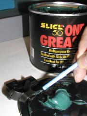 Knowing there is a misalignment, and knowing the cause of the misalignment are two different things. In this case, the bases were on the same plane so everything from the receiver to the two bases were dimensionally OK. The problem was either in the rings, or in the dovetail locking recess in the bases. The ring height check out to be uniform, so I took a stab at rotating each ring 180 degrees from their original position, and reinstalled them without any other changes. I always brush on some high pressure wheel bearing grease to reduce wear and tear on the dovetails. After this minor change, the tolerance stack up worked in my favor, as the ring vertical alignment was right on and no shimming was necessary.
I think the use of alignment rods, or any other tool that will accomplish the same is essential. They are available from a number of sources, single size and sleeved to fit 1″ and 30mm tubes. There are fancier solutions than ring alignment rods, most beginning with the word “laser”, and end with the price tag $100+. Some claim to align the rings openings with the bore, some not, all require the use of the user’s eyeballs to assess if rings are running centerline and perpendicular to the bore. An excellent feature of the basic alignment rods I selected, the batteries never go dead.
Properly Securing Hardware
Loctite is one of those substances that seems to get squeezed into everything, but most hardware is designed to be installed without anything more than a light coating of oil on fastener threads. A properly installed graded fastener is stretched when tightened, or preloaded. The correct amount of preload prevents shock and vibration from loosening the fastener, without overstressing the fastener and causing it to shear. Directly measuring fastener stretch is optimal for installation but, as a practical matter, a torque wrench will indirectly accomplish the same. In short, if inside and outside threads are in good shape, and fasteners are properly installed, Loctite is not required. Why do I know I have converted no Loctite users?
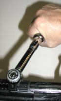
Tightening to a torque spec is effective if both inner and outer threads are clean, free of rough spots and coated with a light oil to insure readings will be accurate. When I checked fastener installation on the Weatherby, where a small L shaped Torx wrench had originally been employed, three were too loose, one was over tightened, none were correct. No one can guess torque, and sometimes torquing is not so straight forward.
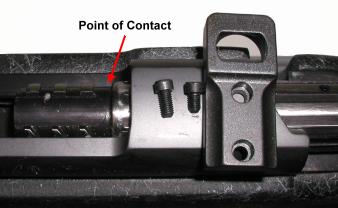 Leupold supplies Weatherby mounts with two fastener lengths they refer to simply as long and short; both are really incorrect for the application. The long fastener thread protrude through the receiver and interfere with bolt travel, the short set grips the receiver with three threads. The minimum number of engaged threads in length should equal the fastener’s diameter, the preferable engagement should fill the hole in the receiver, without protruding through and contacting the bolt.
Leupold’s FAQ reference torque for the Torx fastener is 13~16 in/lbs. The Burris site has an interesting suggestion for fasteners that grab only 3 threads, versus those hanging on by 6 or more; 13 in/lbs for the former, 22 in/lbs for the latter. I elected to go with 13 in/lbs for the short threads, 22 in/lbs for all others, as I have not had a scope shoot loose when I’ve taken the time to torque fasteners to this setting. You don’t have to guess proper torque settings. The “Machinery’s Handbook”, and similar reference books, identify proper torque across a wide array of fasteners, and state proper prep and conditions for installation. They also provide the formula for calculating proper torque in the event the applicable fastener isn’t listed. Note of some interest, save those Torx head fasteners left over from scope installations or removals, they run about $7 each as a replacement part. By comparison, Grade 8 button head and socket cap screws run $7 per hundred.
If you encounter difficulty in locating things like in/lb torque wrenches at a reasonable price, or a supply of graded fasteners at a cheap price, you might try Enco. They carry most popular name brand product lines, as well as generic store brands that are a great value. They also carry machine shop supplies and equipment ranging from large shop CNC milling machines, to miscellaneous material like sandpaper. They have lots of sales, so I usually make a wish list, then wait until the item is offered at a 25% discount before buying. Service is excellent as is phone and email support. No, I receive no preferential pricing or service, in fact, at my level of business I am sure they don’t know I am a customer.
Ring Clamping Surfaces
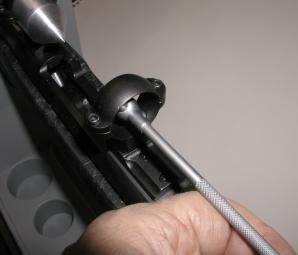 Much is written about constructing uniform ring surfaces that make full surface contact with the scope tube. The idea is that heavy recoiling rifles need every bit of surface contact and clamping power to prevent the mass of the scope from shifting in the rings and beating the optics to death. The typical suggestions are to use specialized reamers or lapping bars to achieve this level of parallelism and surface uniformity. There are a couple of things that quickly become obvious.
Ring openings are egg shaped not round. The non-adjustable internal dimension is always approximately 1″ to insure virtually any 1″ scope tube product will fit (30mm where applicable), the adjustable dimension is always less, something on the order of .970″~.980″ so the interference of the fit will clamp the scope when the rings are tightened down on the tube. The greater dimension, 1″ in this case, will always follow the split of the rings; horizontally split rings will be 1″ side to side, vertically will be 1″ top to bottom. While striving for full ring/scope contact through reaming or lapping of the ring’s interior is a noble goal, removing too much material from the interior of the rings will only reduce the rings’ clamping power. Instructions packaged with lapping bar products typically caution heavily against over doing the process, and note that lapping may not be required in all cases.
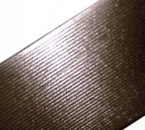 Another reason to exercise caution when lapping or reaming scope rings, some ring manufacturers enhance the gripping surface by adding striations. The idea is that the ridged or raised surfaces will bite into the scope’s tube to aid in retention. The photo on the right illustrates the striations on the inside of a Leupold ring, running perpendicular to the length of scope tube. Reaming or lapping the surface could destroy the effect of these striations, however, if they are not making contact they would not serve their intended purpose. I decided I would shoot for the best of both worlds, lap until there was full contact, even if that only meant until the lapping bar made contact with the tops of the ridges.
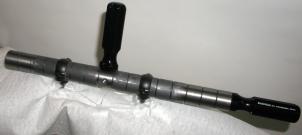
There are a number of lapping bars on the market. The product pictured left is carried byBrownells and runs about $40 with a supply of 800 grit garnet lapping compound. Midway USA has a combo alignment pins/ lapping bar product by Wheeler that sells for approximately $30. I selected the Brownells item because it was made from mild steel, had adjustable handle positioning and relief grooves to collect excess lapping compound. The Wheeler unit is packed with 220 and 320 grit, which I thought was too aggressive for this purpose. It may take a little more effort to remove material with a finer grit, but this is better than taking too much off and having to begin over with a new set of rings.
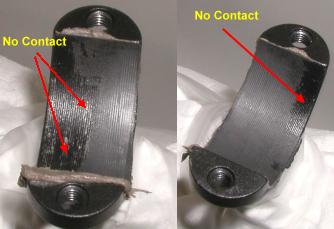
The white crumpled stuff under the rings in the picture above and to the right is a paper towel. Not only are the rifle and mount bases under the rings covered, but all seams are also taped over. Lapping compound is highly abrasive and it needs to stay clear of all surfaces other than the rings. Consistent with the supplier enclosed instructions, I coated the lapping bar with compound, placed it through the rings, tightening the top ring halves only enough so the bar would drag uniformly top and bottom, without the top ring half rocking under the motion of the bar. The bar was cycled fore and aft, while rotated 90° to insure uniformity of contact and metal removal. After 30 strokes, I pulled the bar and checked the ring surface contact. The rear ring, right, actually wasn’t too bad, however, the front ring was making contact on only about half of the ring surface.
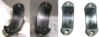
It took about 90 strokes to get to full contact. The reason for the uneven appearance is that I stopped when I had either bare smooth metal or I was in contact with the top ridges of the striations, which left the blued surface in the recesses still visible. Total metal removed was minimal, about .005″, so no clamping strength was lost while the high spots were removed. When I was wrapped up with this step I double checked with the alignment rods and everything was still in good shape. I want to say this step may not be necessary, but I believe the degree of non-contact surface area found in this case made this a reasonable corrective step to take.
Reticle Squaring
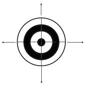
Reticle squaring would appear to be a critical component of scope set up. When a scope’s external elevation and windage adjustments are cranked, the bullet’s point of impact will track, respectively, to the vertical and horizontal axis of the scope’s reticle. If the scope is canted to the left in relationship to the firearm, an upward elevation adjustment of the scope would result in the point of impact shifting up and to the left, rather than only straight up. A right windage adjustment in the same situation would shift point of impact to the right, but also in an upward direction. This step is required if scope adjustment is to be predictable and appropriate. There are tons of crazy tools on the market that are suppose to serve this purpose.
The trick here, I believe, is to stay away from ads for specialized product, and think wood working. All that is required is a straight up and down vertical reference line to make sure that the rifle isn’t canted left or right and that the scope reticle is also straight up and down. No matter what gadgets are offered for sale, sooner or later, they all require some simple external reference for alignment, and an eyeball check for the same. There is no magic alignment tool that will guarantee everything is square without a dependency on an eyeball for verification.
 A good place to find a true vertical reference line is a simple push tack, a length of string and an empty cartridge case. I chose a .45-70, but cartridge type selection is optional Basically, you find a wall some distance from the rifle’s muzzle, 15’~20′ or so, you suspend the case from the end of the string, and tack the top of the string to the wall so the cartridge case will be suspended. The result is a perpendicular reference to the ground; straight up and down. Yes, fishing line can be substituted for the string, as could a real plumb bob or washer for the casing.
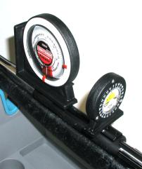
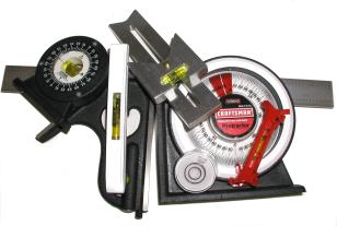
Either one of these tools can be used to level and square the rifle to the earth. The large one is a Sears Universal Protractor, $10, the smaller is an Empire bubble protractor, $6 at any discount hardware store. They are both accurate and both have a magnetic base. The Sears unit is a little more handy because the base is wide enough to span both sections of a two piece base, on a long action rifle, to check for vertical level. The smaller is handy for mounting sideways on a small base to check for horizontal level.
With the bolt removed, I looked through the bore and moved the rifle until the plumb line hung on the wall cut through the center of the bore. Then I carefully rotated the rifle side to side and up and down until both protractors showed “0” degrees. Then I went back and made sure the I could still see the string cut through the center line of the bore; two minutes of actual effort.
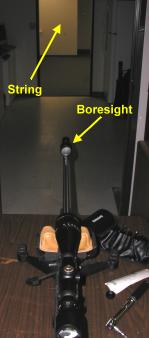
The picture on the left shows the actual setup used for this set up. I took the rifle out of the maintenance vise and moved it to a table supported by a rifle rest and a leather rabbit ear bag. The vise kept pulling the rifle out of position when it was locked down and the rest gave much more flexibility of adjustment. The dark area, followed by the lit area where the vertical string was hanging made the view through the scope more clear and easier to align.
Initially, I left the scope very lose and, without touching the rifle, rotated the scope until it was in perfect vertical alignment with the plumb line. Then I torqued the ring hardware down to 22 in/lbs, staggering the effort and alternating sides. Just pulling my head back from the scope a little to get a broader reference, the scope seem much more critically aligned than when I’ve used the edge of a filing cabinet or window molding for an informal reference. After getting the scope in straight and tightening the fasteners, I went ahead and bore sighted the rifle. With the scope lined up, and useful as a reference, it was much easier to position the bore sight correctly aligned in the bore. I had to adjust about 8 clicks to the left and a similar amount of clicks down (1/4 MOA) to hit the grid at center. While this was quite a shift, it actually brought the scope closer to the center of the adjustment range which, in itself, was an improvement.
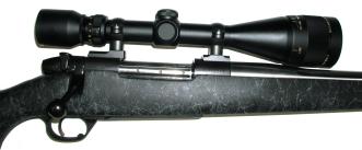
The good news was that a loose scope, rather than a shot out barrel, was probably the cause for deteriorating group size performance; the rifle went back to sub MOA groups. The bad news, I found there was still some reticle horizontal rotation, unfortunately it was caused by my improper hold on the rifle. Practice, practice, practice….
Thanks
Joe

Email Notification