
I recently read an article in a print publication, where the author went to great length to caution people to not work on their own firearms. The author cited his automotive engineer brother-in-law, as a man who refused to work on the family car for fear of putting his family’s lives in jeopardy. Apparently the author, and his brother-in-law, have never met the “highly trained professionals” who populate many of the franchise automotive repair centers.
Don’t attempt projects beyond your skill, don’t work projects when you’re feeling impatient, don’t attempt projects where the end result can’t be objectively tested for performance and safety, but don’t be afraid of your firearms. I don’t care for the publication’s message that a person’s judgment is sufficient to purchase and use a firearm, but not sufficient to determine which work can perform without professional assistance, and which need to be placed in the hands of a competent gunsmith.
The Project
This project began with the possibility that a factory Remington trigger could be limiting my rifle’s potential for accuracy, and that a moderately priced replacement premium trigger could open the door to measurably improved performance. I figured I’d grab the most recent Remington addition to my gun cabinet, one devoid of bolt locks and keys, and see what could be put together. In addition to the trigger component of the project, this was also an opportunity to illustrate how some of the mini machine shop equipment comes into routine use for people with an interest in firearms.
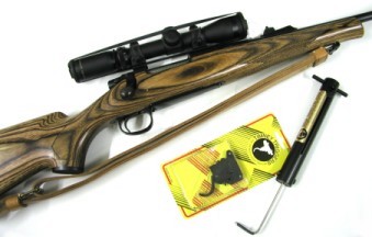 The Remington Model 7 is a solid product. Mine is carbon steel with metallic and optical sights, and has a nicely done laminated stock. The rifle looks good, shoots straight and is very reliable. Yes, the M7 does contain some parts made of modern miracle material, sort of Spam – the mystery meat, and should be replaced. In addition, my Model 7 had a less than exciting trigger.
A trigger job on this type of Remington, typically means cleaning the trigger assembly, placing a drop of gun oil or dusting with dry lube on contact surfaces, removing the Loctite seal and appropriately setting the trigger adjusting screw to a comfortable pull. The trigger stop screw setting can be tuned for over travel at the risk of a bound trigger or gun that won’t cock, however, changes to the trigger engagement screw adjustment is virtually never required, and should be left as the factory and God intended. A Remington trigger would almost have to be defective if it couldn’t be adjusted to any reasonable configuration for casual target shooting and hunting use. In fact, all of my other Remington rifles utilize a tuned factory trigger.
Options and information
 If you are mechanically inclined and want to take a run at adjusting the factory trigger, a copy of “Gunsmithing: Rifles” by Patrick Sweeney, or similar, will provide basic adjustment information, and a copy of “Firearms Assembly, the NRA guide” will provide the exploded drawings and proper part nomenclature for applicable assemblies. If you are mechanically declined, and you know who you are, a quick trip to a local gunsmith and $50 worth of currency separation anxiety will get you the same result. The same comments and information apply in the event you wish to install, or have installed, a third party trigger on your rifle.
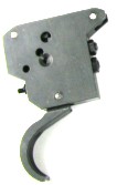 Premium triggers fall into two major categories of design; those based on the original Remington assembly, mostly retaining part geometry, with possibly a moderation of spring weights to shift the trigger pull range. Some of these trigger assemblies may feature improved materials, more precise mechanical fit and finish, and reflect greater care and quality of assembly. The Timney unit pictured on the left is an example of this type of product, it carries of price in the $75 to the slightly beyond $100 price range. While not available as a consumer direct purchase, the Remington factory trigger carries approximately the same retail price.
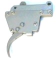 A second type of replacement trigger is made to a proprietary design, a design which may alter mechanical advantage, provide ease of access for trigger assembled rifle adjustment, and incorporate more costly materials in their manufacture – these are intended for more specialized applications. An example of the proprietary type would be Jewell, pictured to the right, a brand that sells for approximately two and one times the price of the Timney.
Within these product lines, triggers are further subdivided by range of pull, typically stated as “Standard” vs. “Competition” or “Bench”. Standard trigger ranges are typically 1.5 – 4.0 lbs, competition triggers are produced in the 2 – 6 ounce range; better quality triggers may offer a slightly wider range of pull adjustment within each type, and may include a selection of springs for tuning pull. I don’t believe a very light pull, or highly refined features, have much of a practical application in a rifle intended for any purpose that does not include patient, near stationary shooting. Therefore, I selected the Timney as a more appropriate trigger for comparison to the factory unit, a type more frequently installed in general purpose rifles.
The retail price, at this time for PN 883-400-270 blue Featherweight trigger is $86 from Brownells and $62 for the same product from Midway USA. A nickel plated version can be purchased directly from Timney at the Brownells’ price and, no, I don’t know what all of that retail price inconsistency is about. The hand honed Timney Featherweight product is spec’d as adjustable for pull between 2 and 3.5 lbs, and adjustable for creep and backlash. I placed an order with Brownells …..then waited 3 months for delivery.
Initial impressions when received
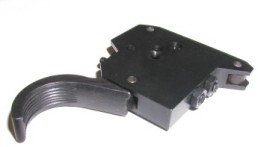
Installation of a trigger assembly may not be a drop-in proposition. The Timney installation instructions noted that it may be necessary to re-drill trigger mount holes if they do not align with corresponding points on the rifle. The Timney trigger is wider than the Remington part so care must be taken to insure there is no contact; the trigger should float and not bind  in the stock. In addition, the opening into the trigger guard needs to be checked to insure there is clearance. The flip side of the Timney one page instruction sheet indicates the M 7 receiver has a shorter locating slot for the trigger housing than the Model 700, which means the Timney housing may have to be trimmed to fit. A simple trigger swap may branch into minor stock inletting, metal rework and refinishing of the reworked parts.
I wasn’t all that excited about the quality of the Timney trigger assembly. The trigger had been short shot in the casting process, leaving a ragged edge where it entered the trigger housing, giving the appearance of a broken part. The Timney’s sear safety cam is honed, but Remington provides a smooth plated cast piece which means a marginal difference in friction reduction through honing, and the factory plating would provide a harder surface, which means greater wear resistance. The Timney sear spring is shorter, lower tension than the factory part, which means a reduced initial pull. I didn’t care for Timney’s “one size trigger housing fits all” Model 700/7 approach. This customer fitting requirement wasn’t made necessary to accommodate normal dimensional variations found in the factory assembly, this was Timney placing a burden on the customer to produce what they had avoided, namely a second trigger specifically designed for use in the Model 7.
Digging in
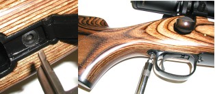 After first checking the Model 7 for empty, I measured the factory trigger pull at 6 3/4 lbs, then 5 lbs, then 6 lbs. Then I added a drop of oil which brought the pull to a consistent 5 lbs. Some of the most impressive gunsmith accomplished trigger jobs are the result of a very small drop of oil, or dust of dry lube. Let’s see, $50 per drop….
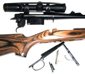 The Model 7 comes apart easily with the removal of two Allen head screws, one in plain sight, the other located under the magazine floor plate. My scope is on Warne quick detachable mounts, so it came off in a few seconds. Once the hardware was separated from laminated stock, I found lots of factory protective gunk in there, which caused me to bow my head in shame for having missed this on the initial cleaning. On the plus side of the ledger, the quality of the parts hidden from sight in the assembled product, is very good; inletting, finish, bluing and hardware. The floor plate assembly is bad, incredibly cheap looking and destined for eventual replacement.
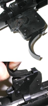 It is easy to become the victim of unintentional or sudden disassembly; stuff falls off or flies through the air inadvertently, and it isn’t always easy to recall all of the original part positions. Taking pictures during the disassembly process, may be the difference between a successful project, and a box of loose parts on their way to a gunsmith for reassembly.
The upper portion of the picture on the left, shows the Remington safety coming down from the receiver to the trigger housing where it is anchored by a safety snap washer, or spring clip. The spring clip holds the safety detent ball, detent spring and safety in place on its pivot. The detent ball creates positive location of the safety when placed in the “Safe” or “Fire” position.
The lower photo shows the bolt stop release that, for bolt removal, lowers the spring loaded bolt stop that is pinned to the receiver. The pivot pin that locates the release lever passes through the trigger housing and through the safety.
Great care should be exercised when disassembling. This Timney trigger is not supplied with safety or bolt release hardware, but rather relies on the transfer of the parts affixed to the rifle’s original factory trigger. This is only of consequence because Remington lists these parts as available only to authorized repair centers, and not directly to consumers. So if you deform the safety snap washer, and render it useless, you will not be able to purchase another directly from Remington parts supply.
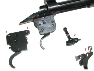
With the safety and bolt release lever components removed, the Timney unit on the left, begins to look more like the Remington factory trigger assembly that remains connected to the receiver by two pressed pins at locations #4.
The Timney trigger comes with two temp locating pins, #1, that hold the sear safety cam and sear spring in place prior to installation. #2 is the removed safety and detent ball, #3 is the bolt release lever, pivot pin and safety snap washer.
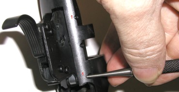 The trigger assembly mounting pins, #1, are tapered on one side and tap out right to left with a long straight punch. The Timney instruction sheet noted that pins should require very little pressure for installation, or mounting holes in the Timney trigger should be drilled to fit. Actually Remington pins are correctly a light press fit.
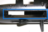 With the Remington trigger removed, you can see the recess, framed in blue, that locates the trigger housing to the receiver. A quick trial fit with the new assembly confirmed the housing would need to be trimmed to fit the receiver properly. Again, this rework is only necessary for fitting this model Timney trigger to the short action Model 7, not the Model 700.
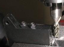
I was getting the trigger housing ready for trimming, when I realized I could correct the appearance of the ragged Timney trigger casting. I didn’t want to install the new assembly the was, as it seemed unreasonable to spend nearly $100 to make a gun look worse.
I clamped the trigger assembly in the milling machine and used an end mill to cut a nice even machined edge. A little touch up flat black and the trigger looked better than new.
I placed a light coating of Dykem Blue layout fluid on the areas that would approximate the excess material of the Timney trigger, in anticipation of marking scribe lines on the new part. Layout fluid makes scribe lines really standout on the work piece.
Since the original trigger correctly fit the receiver, it’s mounting holes were used as the reference points to transfer all other housing profile dimensions. I put a close fitting punch through each mount hole in the untrimmed Timney trigger assembly, overlaid the properly dimensioned Remington trigger assembly, then followed the outline of the factory part with a scribe to transfer the factory trigger’s outline to the Timney trigger assembly.
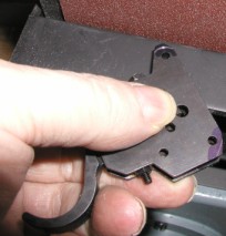
The work surface was curved, so I used the belt sander to remove excess material and shape the Timney trigger housing. A small flat file and Arkansas stone cleaned up any burrs, the sander marks were removed with a little 600 grit “wet or dry” paper. Some cold blue touched up the bare metal surface and provided protection from oxidation.
This may seem like a lot of work, but it was actually very enjoyable. These types of tasks can provide a lot of satisfaction, especially when they come out right. I figure any time I don’t unintentionally saw through a barrel, or skip a checkering tool across the cheek piece of an almost finished stock, I may as well pat myself on the back for doing an okay job.
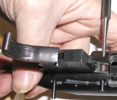
The newly modified trigger did not drop into place. I used a 1/16″ drill to clean up one mount hole, then, a punch to line up the holes and wiggled the pins to coax them through the receiver/trigger sandwich. The Timney instruction sheet suggests leaving the keeper pins (the ones that retained the sear safety cam during shipping) in place while assembling, driving then out as the rifle’s mount pins are driven in. The problem is the Timney pins are square shouldered and easily misalign with the receiver holes. The rifle’s mount pins are heavily tapered at one end, so they start easily and pull the trigger housing into aligned position with light pressure.
A note on hammers. The only general purpose hammer I keep in my tool box is a 4 ounce Ball Pein with a hickory handle. After being found guilty of pin homicide on several occasions, I found having only a light 4 ounce pounding option mostly solved the problem. Although I’m sure some serious enthusiasm and an uncooperative pin could still result in a pin to rivet conversion. In this case, a light tap to seat the last .030″ or so was all that was required.
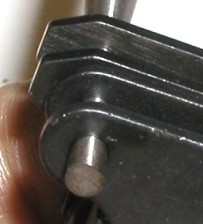
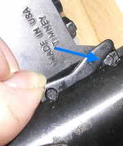 The Timney instruction sheet indicates the mounting pins should slide in with finger pressure, but I think probably not. Here you can see the pin head, not quite seated, and holding up the bolt stop in the “don’t stop” position. I would want to make sure the pin is flush, and that it was retained with enough pressure to keep it in place…or that I had a really clever retort for those times when the bolt might accidentally fall out on my foot in a public place, in the middle of a crowd…like at the rifle range, or hunting camp.
With the trigger housing properly in place, the next step is to add the rest of the small parts that make up the trigger assembly; the safety and the bolt stop release lever.
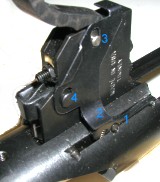 To reassemble, the bolt stop #1 is pushed down into its recess, and the bolt release lever #2 is pressed down on top of the stop and slipped over the trigger pin #3. While you hold the release lever in place with one hand, you use your free hand to slip the safety over the other side of the housing. Then you use yet other free hand to insert the pivot post #4 through the release lever and through the safety. The pivot pin head is stepped to provide clearance for the release lever so it will not bind when the rest of the hardware is locked into position. Yes I do know I referenced three hands, but I’m assuming some level of dexterity and at least a few functioning digits will provide the necessary tools.

Here you can see the safety located by the pivot pin, then the detent ball dropped into place, then the detent spring placed on top of everything.
 The safety snap washer goes on easier if it is started off the edge of the detent spring, then rotated over the spring until both indexing bumps can be seen through the washer, as pictured in the photo to the left. These little bumps will insure the part does not rotate out of position and work loose from the assembly.
New trigger adjustment
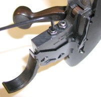
This Timney trigger model ships from the factory with pull preset to 3 lbs. Measured with a pull gauge, mine initially released at about 2.5 lbs with cleaned and lubricated contact surfaces. After 5 or 6 cycles, the required force increased to 3.5 lbs and became very consistent.
On the right is the wrench in position to adjust pull. The lock nut is loosened and the center hex screw is turned counterclockwise to reduce pull, clockwise to increase. I set the trigger to 3.25 lbs., where it remained. The actual adjustment was made with the action is a padded vise to insure an accurate pull gage reading. Trigger pulls adjusted too lightly, to close to the intended pull range for the trigger can result in slam fires, the gun discharging as the bolt is closed, without the trigger being depressed. Timney defines 2 lbs as the minimum pull for this particular product. Personally, 3 lbs is my low limit for my sporting rifles, I have a difficult time shooting firearms with very low trigger resistance.
There are two other potentials for adjustment on the Timney trigger, the first is overtravel; limiting trigger travel beyond what is required to release the firing pin. The idea is to minimize firearm movement as the gun discharges. The adjustment is directly above the pull adjustment screw. Overtravel adjustment on this particular trigger was perfect as received. Too much of a reduction in travel can: slow or stop firing pin motion, cause the trigger assembly to bind and lock up or cause the rifle not to cock when the bolt is rotated home. The final adjustment isn’t really a gun owner’s adjustment, sear engagement, or how big of a bite of metal holds the trigger parts in position when the bolt rotates closed and the rifle is cocked. After doing some single action revolver work, and seeing very small contact surfaces at work, I have developed a great respect for them and leave them alone and, quite frankly, unless a trigger is defective and requires the work of a skilled and experienced gunsmith, there just isn’t enough practical potential to go after.
Simple reassembly…perhaps not
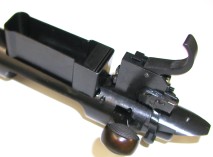
Sometimes the biggest problems are those not highlighted or footnoted within instructions. In addition to the material that was noted by Timney for trimming, the leading edge of the Timney housing is machined at a right angle, while the Remington part is angle cut to clear the inside of the Model 7’s trigger guard. On Timney triggers that do not have external adjustment capability, this portion of the trigger housing is a solid piece of carbon steel, and the interference became obvious on trail assembly.
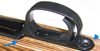 The trigger guard contacted the leading edge of the Timney trigger and would not seat flush in the stock. As I learned from a run-in with an ancient Marlin M1 carbine looking rim fire some time ago, it is not a good idea to tighten an inexpensive cast part into physical conformity. The part will crack, and the person who did the cracking might spend the next two years trying to locate a replacement.
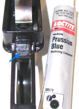 I brushed a little Prussian Blue on the front edge of the trigger, and lowered the guard into place. The Prussian Blue transferred to the trigger guard assembly, indicating exactly where there was contact, a point where I would have to create more clearance. The dilemma was, which part to modify.
Actually, the only dilemma was finding a rationalization that would get me out of removing the trigger I had just installed. It is better to modify an add on part, especially one that is out of dimensional compliance with the original part, than to permanently modify the original parts of a rifle.
It took about 5 minutes to remove the trigger and set it up in the milling machine. When I first installed this equipment, I had the mind set that I would be using it mostly to fabricate new parts and assemblies, I hadn’t realized how often they could be used for this type of work.
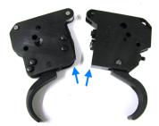 I used the Remington trigger, again as a template, to identify how much material would need to be removed from the Timney. I used a machinist’s combination square to point the corner straight up in the machinist’s vise, so I would cut a 45 degree flat and move material away from the trigger guard.
Where the Remington trigger housing is made of two pieces of stamped steel, the Timney housing is machined from solid stock with more than sufficient room for safe trimming.
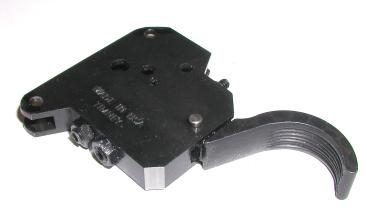
The finished modified trigger, right, looks pretty clean. I know this seems like a simple task, but it represents greater independence in working on my own firearms, and much more control over the outcome. In my part of the woods, there are no places to drop in and request minor machine work, now I have access to much better solutions I can implement.
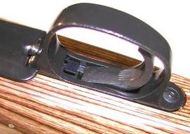
I received mail from people who want to know how often the Micro Mark milling machine gear drive system breaks or requires maintenance. The answer is never, and I use the equipment frequently. I am very much aware this is a small machine, so I try not to overload it. In this case, I made a few .010″ passes, rather than taking one big chomp out of the material. I not in that big of a hurry. With the minor machining out of the way, I reinstalled the trigger assembly, plopped on some more Prussian Blue and checked for remaining contact with the trigger guard and stock; everything fit together correctly. Below is the finished product after everything was reassembled. There is no binding or bowing, rough parts or bare metal showing and all hardware is flush with the stock.
 The rifle felt more comfortable to shoot with the reduced trigger pull and crisp release. Compared to the original trigger, as received from the factory, not much was picked up at the bench in the way of smaller groups or consistent shot placement, but results when shooting from the standing position improved considerably, perhaps an inch or more in group size. The pull was very uniform, shot to shot, and the let off was very clean.
For comparison, I reinstalled the original Remington trigger, adjusted the pull to 3.25 lbs and got the same feel and shooting results as the Timney. Considering the price of the Timney trigger and the hours spent on installation, I don’t believe I’d do it again. I’m returning to my use of tuned factory Remington triggers and wait until I have a rifle where use of a Jewell trigger would be appropriate, before I try this again.
Was the project a waste of time and money? Not at all. I learned a lot about my rifle, I learned a lot about triggers, I was able to get some first hand information on replacement assemblies, and I was able to use my milling machine for a useful purpose. It was a lot of fun.
Thanks
Joe

Email Notification