I like the AR-15. Slow coming to the party, I’ve learned to appreciate the mechanical design and performance of the firearm, as well as the gun’s versatility and inherent accuracy. Building a few with specialty parts has been a source of enjoyment and the results, in terms of quality and accuracy, have been excellent. That’s saying a lot coming from a guy with modest firearm building skills. If there is one remaining issue for me, it’s that the AR-15 goes pop, pop, pop, when I’d prefer it went boom, boom, boom…which pretty much led me to AR-10 type firearms like the LR-308 and the recent ammunition introduction that has added a lot of promise to the big .308 Winchester gas guns.
The release of Hornady’s Superformance ammunition has given the .308 Winchester a lot more punch which has correspondingly extended the AR-10 type rifle’s range without adding the cost associated with more specialized larger bore cartridges.
| Cartridge |
Manufacturer
Type |
Bullet
Weight |
Ballistics
|
Range – Yards |
| 0 |
100 |
200 |
300 |
| .223 Remington |
Winchester
Super X |
55 |
Velocity |
3240 |
2747 |
2304 |
1905 |
| Energy |
1282 |
921 |
648 |
443 |
| Trajectory |
-1.5 |
1.9 |
0.0 |
-8.5 |
| .308 Winchester |
Federal Fusion |
150 |
Velocity |
2697 |
2483 |
2280 |
2087 |
| Energy |
2422 |
2054 |
1731 |
1451 |
| Trajectory |
-1.5 |
2.1 |
0.0 |
-8.8 |
| .308 Winchester |
Hornady
Superformance
SST |
150 |
Velocity |
3000 |
2772 |
2555 |
2348 |
| Energy |
2997 |
2558 |
2173 |
1836 |
| Trajectory |
-1.5 |
1.5 |
0.0 |
-6.9 |
Shooting .308 Winchester Superformance 150 grain and 165 grain loads produced velocity levels in my bolt action rifles that exceeded traditional .30-06 Springfield performance and the gain was accomplished without exceeding SAAMI .308 Winchester pressures. Almost like a great exercise program that doesn’t require getting up from the living room sofa. It seemed like a good time to start a long range AR type shooter project, unfortunately, my area of firearms’ expertise was mostly limited single shot Savage shotguns produced between 1956 and 1957. Where to begin?
Brains in a box…for kits in a box

One of the benefits of purchasing materials from Brownells is the access to all of the information they make available to their customers. With this type of product support, I’ve been able to attempt and successfully complete projects that would otherwise have been beyond my technical reach… and I had really short arms when I began working on firearms. In the specific case of AR type firearm, Brownells has developed the AR-15 Builder, the dedicated
AR15/16 catalog, online professionally produced technical videos and appropriately illustrated articles.
Brownells also carries a solid selection of technical training manuals and DVD’s and Brownells’ tech people are always close by to answer tech and product feature related questions. Regardless the nature of the question, I’ve always received a professional, polite and timely responses which is a retail and commercial rarity these days. I began this project with AR-15 some modification and accessorizing experience, but no AR-10 experience and no lower receiver build up experience with either model. The LR-308 is very similar to the AR-15, however, there are some differences.
Sometimes purchasing is the best way to save time & money…
The DPMS Panther Arms upper assembly provided all of features that were of interest to me and at a price that would be hard for me to improve upon by putting one together from scratch. Available in 16″, 20″ and 24″ barrel lengths, all DPMS assembled models feature a thick walled receiver made from extruded 6066 T6 aluminum, hard coat anodized and Teflon coated. The 24″ model has a free floating handguard and a 0.920″ OD 24″ long bull barrel made of natural finish 416 stainless steel that is capped with a recessed target crown. The receiver is topped with a Picatinny rail, as is the gas block, making it easy to mount any form of optical or metallic sight system. The upper has a smooth-side receiver, no ejection port cover, shell-deflector, or forward assist which is appropriate for the application. The upper assembly is listed as Brownells SN 231-000-236. Wanting a long range shooter to take advantage of the newly found .308 Winchester potential, this is the model I selected.

Below is a pretty good illustration of the difference between the 5.56mm and 7.62mm uppers. The difference in action length, 7.75″ and 8.75″ respectively, is more obvious as is the standard barrel diameter of the 5.56 compared to the bull barrel of the 7.62mm; 0.775″ and 0.920″ respectively.
Selecting a lower receiver, a number of possibilities…
Brownells offers five lower receivers for LR-308 applications, three are from DPMS, two of which are complete lowers with either fixed or collapsible buttstock, one is stripped; 231-000-234, 231-000-233, and 231-000-245 respectively. Additionally there are stripped receivers from Patriot Ordnance Factory and CMMG, Inc. These latter two are compatible with DPMS, Remington, Bushmaster, and Patriot Ordnance Factory uppers and/or magazines. I passed on a complete lower assembly because the plan was to assemble more to personal preference and to gain experience by building up a lower. All three stripped receivers are made from 7075 T6 aluminum billet, reinforced in high stress areas and all accommodate 0.275″ pivot/takedown pins. All are well made. In the end, the choice became a matter of aesthetics, both form and finish. From a price standpoint there isn’t $10 separating them in price. The CMMG part was the final choice because it is sculptured around controls, the hard anodized matte black Teflon finish looks good and it has an oversize trigger guard.

As received there were no rough areas or undersize/oversize dimensions. The stripped lower fit up cleanly to the upper with no rework whatsoever. Everything was tight and hole size and alignment were correct. Looks nice.
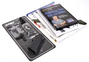
Brownells SN 231-000-250, Lower Receiver Parts Kit contains all of the parts necessary to build a stripped LR-308 lower into a functioning assembly. Beyond LR-308 specific take down and pivot pins, bolt catch and bolt catch screws, there are a number of heavier weight springs, as well as a heavier hammer that are required for reliable .308 Winchester round ignition.
This type of kit is a good way to ensure everything will work when a gun is initially put together, while keeping the investment small enough so that the additional cost of future individual part upgrades would not be considered wasteful. As an example, I purchased an accessory grip, not pictured, that is more to my liking and a refined trigger function is part of a my future plans for the rifle.
The following is an overview of assembly, hopefully pointing out some points of consequence. In all third party instructional documentation there was reference to filing, cleaning, fitting and adjusting to compensate for dimensional run out in castings or parts. I did not encounter one circumstance with the lower receiver or the parts kit that required such rework. Everything was drop in, precise in fit and cleanly finished. This is an oil as you go assembly so each part was treated appropriately.
Magazine catch assembly…
The magazine catch assembly, DPMS nomenclature, is comprised of three parts, the magazine catch, the magazine catch spring – the largest in the kit, and the magazine catch button. Installation is identical to the standard AR-15 procedure available in video form on the Brownells site. The catch is slipped through the receiver, left to right, the spring is slipped on from the right side, then the button is pressed into the recess and against the threaded portion of the catch, while the catch is rotated clockwise to tighten. The job is done when the tip of the catch is slightly below the recessed face of the button and an inserted magazine can be cleanly and easily released. If there is a caution it is to make sure the button is pushed in far enough to prevent the catch from marring the receiver as it is being tightened.
Bolt catch assembly…

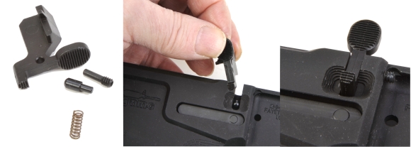
This is a four piece part assembly comprised of the .308 bolt catch, .308 bolt catch screw, bolt catch spring and bolt catch buffer. Installation differs from the AR-15 in that the LR-308 is retained with a shoulder screw rather than a driven roll pin. There are two small springs of this approximate size in the kit. The uniform diameter spring is the correct one for this assembly. The spring is dropped into the receiver well, the buffer is dropped in with the big end up – I used tweezers after the fourth attempt, then the catch is pressed into position. The unthreaded shaft of the screw allows it to be used to locate the catch in position and held before it is necessary to use a 1/16″ hex wrench to tighten it down. I put a half drop of blue thread locker on the thread just before tightening. It is a shoulder fastener so it can be tightened all the way without impeding movement of the catch. The bolt catch is ops checked for full travel without binding, magazine in or out.
Arghhh, Maties! It’s the devil’s detent I tell ya…
There are two pins that hold the lower receiver to the upper on assembly the .308 front pivot pin and the shorter .308 rear takedown pin. To prevent each from inadvertently falling out, while allowing ease of movement for disassembly, the pins are held under tension by a combination of steel takedown detents and detent springs (top left) that reside in wells in the lower receiver adjacent to the pins (top right for pivot pin). The methods used to retail the detent assemblies are not quite the same as those used for the AR-15 which changes the approach to installation.
The aft takedown pin detent and detent spring installation are a snap to install, a process that is covered later in this piece where appropriate within the assembly sequence. Installation of the front pin is easy if you were smart enough to buy the $15 installation tool, Brownells SN 080-216-011, Pivot Pin Installation Tool. Inexpensive and readily available, only a person not paying attention when preparing for a project of this type, that would be me, would overlook its usefulness. In this case, working on the weekend and too impatient to order and wait for the mail, I made my own by cutting the head from a snow blower shear pin then turning it down to 0.275″…really. OK, any excuse to crank up the lathe.
Looking at the picture top right for a moment, it becomes apparent that it is impossible to stuff a spring and detent into the well in the receiver as, unlike the AR-15, the detent spring and detent must pass through the face of the pivot hinge. Unsupported, the tiny parts will only…Boing! out of the side, or pop into the air, end up on a carpeted floor with the installer crawling around with a flashlight at 10 PM trying to find them. A better approach is to to insert a cross drilled shaft through the receiver hinge to provide lateral support to the spring while it is pushed into place with a small diameter punch, above photo, bottom left insert. Once the spring and detent are pushed into the receiver far enough to clear the tool, the tool is rotated, preventing the detent assembly from popping out, then the rifle’s pivot pin is used to push the tool out, right to left. The pivot pin will then be retained by the detent assembly.
That would be, “What is the name of Roy Roger’s Horse?”, Alex. 
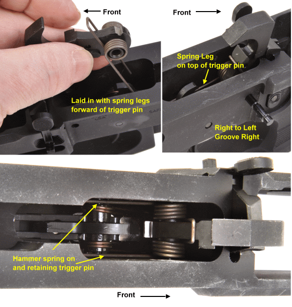
The trigger and disconnector are a five part assembly as shown above and the same to assemble as the AR-15. The trigger spring pops on easily into this orientation. The small disconnector spring, that I cleverly positioned under the…disconnector, is actually inserted into a small well on the top side of the trigger casting. I placed it here to show the big coil on the bottom orientation and the assembly it preloads.

This was an easy part of the assembly process. The trigger drops in with the spring legs extended and the trigger pin is started through the right side of the receiver and into one side of the trigger, leaving the center of the trigger open for the disconnector to be dropped in. The disconnector spring is put in place in the recess in the top of the trigger body and the disconnector is lowered into place, aligned with the cross pin hole in the trigger. The trigger pin is then pushed all the way through, securing both trigger and disconnector. The trigger is checked for free travel, as is the disconnector and the trigger spring legs are checked to ensure they are approximately parallel to the sides of the receiver for clearance and freedom of operation.
I’d rather be a hammer than a…
The hammer is a three part assembly. But Joe, there are only two parts in view. Yes, and thank you for pointing that out. The hammer is preassembled with a “J” spring that passes through the edge of the hammer’s cross pin hole and locks the hammer to the pin when it is assembled into the receiver. This assembly is handled the same as the AR-15. The hammer spring slips over the bosses that receive the hammer pin in the orientation shown.

The hammer is another easy install part. The hammer spring legs are placed in front of the trigger pin, then the hammer is pressed down and aft into alignment with the hammer pin holes in the receiver. This requires some effort as the hammer spring winds up with quite a bit of resistance. Once aligned, the hammer pin is fed in right to left, pushed until the end is flush on the other side. In place the hammer spring prevents lateral movement of the trigger pin and the “J” spring in the hammer prevents the hammer pin from moving laterally. Neat! The ops check is pushing the hammer down, hanging onto the hammer, and pulling the trigger without the hammer slamming against the receiver. There should be no bind and there should be full travel.
Uh-oh, there is…stuff left over. Hmmm
Actually, there are only a few parts left and they get installed into in the bottom of the receiver, under the grip. Top – Selector, selector detent and selector spring. Bottom – .308 rear takedown pin, takedown detent, takedown spring which differ in assembly from the AR-15.
.
This is another straightforward assembly. The hammer is cocked and the selector is inserted in the frame, left to right, and rotated to the “fire” position. The lower receiver is inverted, a little light gun grease is placed in the larger of the two detent wells and the selector detent is dropped in, pointed side down. The selector detent spring is placed on top of the detent. A little grease is placed in the rear takedown pin detent well, the .308 rear takedown pin is installed in the receiver, right to left, and the takedown detent is dropped into the well. It is double ended pointed so there is no up or down orientation. The takedown pin detent spring is inserted. The grip is slipped into position, taking care to feed the selector detent spring into the corresponding well in the grip and ensuring the takedown pin detent spring is pushed down into the well in the receiver without being bent or otherwise distorted.
Now this looks a little more familiar…
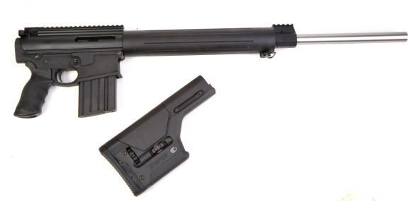
Not quite finished yet, a little more assembly ahead, but the lower tightly joined the upper and they look very good together. A few more parts to connect the two pieces below, a sighting system or two and the gun will be ready for operational checkout.


Email Notification