The problem with working on Cosmoline soaked WWII relics is that the process is addictive. Projects often begin a new learning experience and the work can be very challenging and sometimes lead to irrational verbal berating of inanimate objects. Still, many projects conclude with improved firearm appearance and function. However, while the light of satisfaction burns brightly, it burn briefly, and sends us off in search of the next project. Like Mauser bolt therapy… 
The Mauser M24/47 project has taken on a life of its own. The more modifications made, the better the rifle works, the harder it is to leave well enough alone. The original safety began to bother me, almost as much as that bolt handle. The bolt handle gets in the way for any type of shooting other than during range time and both the handle and safety resist the notion of mounting a scope. Since I need to teach myself to weld before I can fix the bolt situation on my own I decided to go to work on the safety and came up with three potentials.

| # | Manufacturer | Description | Brownells PN | Type | Cost |
| 1 | Timney | Buehler Style Low Profile | 883-804-098WB | Two Position | $39 |
| 2 | Glen Chapman | Swing Safety Conversion | 201-100-098WB | Three Position | $27 |
| 3 | Dakota Arms | M70 Shroud & Wing Safety | 359-141-070WB | Three Position | $150 |
Timney – This is an updated version of the once very popular Buehler Low Safety that ended up on a lot of sporterized Mauser actions. It is easy to install, but it is two position rather than three and it still rotates up toward a scope’s eye piece.
Glen Chapman – From a project standpoint, this may be interesting as it requires machining, heat treating and several other more sophisticated techniques. The parts cost is low, the labor content is high and it is most successfully accomplished with the aid of a Glen Chapman Safety Milling Fixture, Brownells # 201-100-000WB. Basically, the Mauser bolt sleeve is cross slotted and fitted with a horizontal motion wing safety.
Dakota Arms – The cost is initially higher, but that might not be so when viewed as an entire project. The benefits the Dakota Arms pieces hold over the Timney piece are horizontal motion that will clear any scope and all three safety positions. The benefits the Dakota Arms part holds over the Glen Chapman piece are: no need for a $50 milling fixture, no extensive mill work and a much nicer looking finished product. This time around we went with the Dakota Arms part, however, the Chapman piece is in the schedule as we could not walk away from the challenge.
Installation… in short form
In the world of packaged instructions, Dakota Arms looms large; one piece of paper, 7 steps and three small but adequate reference drawings… for anyone who understands Mauser function and how the safety relates to other systems like the gun’s trigger. So I combined the Dakota Arms instructions with the AGI Building the Custom Mauser Rifle DVD Brownells # 050-120-306WB, which specifically covers installation of this type of assembly and all of the associated assemblies. Then I had lunch; low fat ham and Swiss, Swiss on top, then shredded lettuce, a thin slice of tomato, and a table spoon of mayo, all on a Kaiser roll. I wonder what we are having for dinner? Anyway…
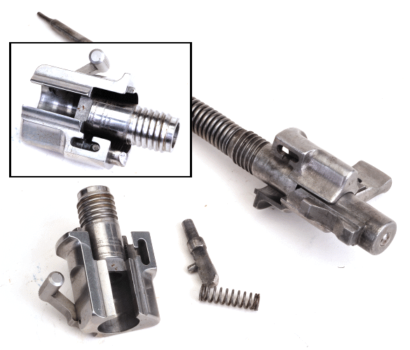
With the firing mechanism cocked and the safety in the straight up safety on position, the bolt sleeve locking plunger is depressed and the original firing mechanism is unscrewed and removed from the bolt body. The locking plunger is then transferred from the old bolt sleeve to the new bolt sleeve as show in the inset photo. The new bolt sleeve, without the firing pin or cocking piece is screwed into the bolt body.

The partially assembled bolt with new sleeve assembly is inserted in the rifle and closed. The check is to see if the underside of the sleeve drags on the receiver or if the if there is enough compression of the bolt sleeve locking plunger to allow the locking lugs to cam and lock with a fully closed bolt. These kinds of steps are important because they take other assemblies out of influence, which helps with trouble shooting when required. In this case, the sleeve fit correctly and needed no further attention. As I will cover, later, if the firing pin spring had been in place the bolt would not have closed and I would not know specifically which component was the cause.
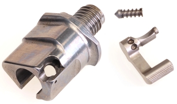 There are a couple of reworks noted in the instructions that we held off performing until they were deemed necessary. There is, however, one rework that is required regardless the individual rifle part fit – relieving the end of the bolt body to accommodate a bolt lock plunger that is introduced with the new bolt sleeve assembly.
The flat end of the spring loaded plunger passes into the bolt and stops it from rotating when the safety is in position three; safety on, bolt locked.

Top left photo, the original safety lever is scalloped on two sides so that it clears the bolt when off or in safe position one, but rotates into the recess in the bolt body to prevent the bolt from opening when the safety is rotated all the way to position three; safety on, bolt locked. Pictured center, the location of the safety lever shaft in the original bolt sleeve. Far right, the location of the bolt lock plunger that replaces the safety lever in performing the bolt locking function with the new bolt sleeve. The plunger requires a corresponding half circle relief to be cut into the bolt body with either a 0.125″ diameter mill or Dremel grinding bit to a length of 0.070″.

The Dakota Arms instructions are precise for the rework with size and placement of the bolt relief, however, the placement is based on a bolt body centerline, which assumes the installer is equipped to find the bolt centerline. The AGI Building the Custom Mauser Rifle DVD offered a simpler and probably more accurate solution that I freelanced a bit.
With the bolt sleeve removed, the back end of the bolt body was gone over with a fine Scotch Brite pad to remove any surface oxidation and gunk so marking dye would show. Then the new bolt sleeve stripped of parts, including the safety lever and bolt lock plunger, was installed on the bolt.
The bolt handle was rotated down to the fully locked position and a 0.114″ pin gauge, with Persian blue marking dye on its tip, was pushed through the bolt lock plunger bore and against the back of the bolt body. The pin was used because the bore is stepped and the pin assured better alignment. Then the pin was removed, the sleeve was removed, and what remained was the blue half moon mark at the edge of the bolt as it appears below, in exactly the right location. It’s about 30° off perpendicular. In preparation for cutting/grinding, it is important to note that this is hardened steel.
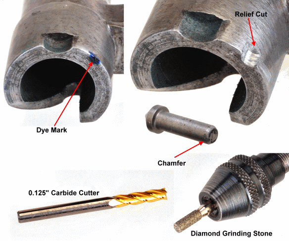
There is an F fixture that is made to properly hold the bare Mauser bolt in a milling machine for this operation, but I could not locate one. This type of carbide cutter does not work well chucked in a grinder; too much tooth and it will walk all over the place. An inexpensive… cheap, diamond stone of approximately the same diameter, chucked in a Dremel made this an easy task. The relief was deburred and edges stoned to remove sharp edges and the bolt lock plunger tip was chamfered to make it self aligning. The location and radius of the relief and pin should be a close match so a lot of slop isn’t present when the bolt is locked.
 Depth of the plunger relief isn’t critical in terms of being too long. The Dakota Arms instructions indicate 0.070″. The DVD suggests 0.100″. There just has to be enough for solid engagement. But the pin can’t be too long or it won’t retract and the bolt will hang. To check, the bolt lock plunger and return spring are inserted in the bolt sleeve, the safety lever is inserted in the sleeve and that assembly is installed on the bolt.
Position 1, the bolt handle should rotate freely. Position two, the safety should be engaged, but the bolt should open. Position three the safety should be engaged and the bolt locked closed. If position 1 had failed, the locking plunger would have been shortened.

To make life easy, and to reduce the complexities of forward trouble shooting, the sleeve and bolt were assembled with the firing pin and cocking piece in place, but now firing pin spring. This demonstrated that the cocking piece locked into the firing pin lugs and cleared the back of the sleeve when turned to lock in place. The tiny roll pin goes through the side of the sleeve and locks the safety lever by a groove in the safety lever’s shaft. Pictured above right, the roll pin holder, lower, makes starting tiny pins a snap and the roll pin starter makes it easy to seat them. Brownells #080-685-000WB and 080-000-241WB respectively.
Incoming!
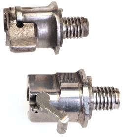 When trial assembling the firing pin mechanism, I found that even if I compressed the spring to coil bind I could not get enough clearance to install the cocking piece. Head scratch, head scratch… Since the only change from when the parts did go together was the addition of the firing pin spring, this areas seemed the right place to start looking..
The culprit was the +0.043″ greater length of the threaded portion of the sleeve. The front end of the sleeve acts as a firing pin spring seat and its extra length was compressing the firing pin spring to coil bind. The coil bind prevented the cocking piece from lining up with the lugs on the firing pin. The coil diameter of this firing pin spring is 0.058″, so I used a small cut off saw to remove one coil and stoned the end to get to a flat seat. This was the only modification necessary to complete assembly of the firing pin mechanism.
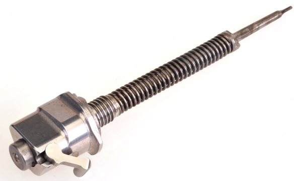
 The firing pin mechanism was then installed in the bolt, the bolt was inserted into the rifle and cocked. Unfortunately, the safety would not engage without the use of a very large hammer. No, I didn’t try one, but that seemed appropriate for the degree of resistance. Hmmm… One of the Dakota Arms recommended reworks is to make a 25° cut on the right side of the cocking piece to act as a camming lead for the safety lever.
The bevel was made with a stone. I put the part in a vise, using an angle finder to get the right tilt, then stoned parallel to the vise jaws. Yes, a run on the milling machine would have been more precise and it would have sounded much more impressive, but it is nice to be able to complete these jobs with hand tools.
The pieces were reassembled and the safety engaged positively in each position. However, when I pulled the trigger with the safety released the cocking piece did not release. Head scratch, head scratch some more. I finally was able to trace the problem to the cocking piece sear engagement ledge positioned forward enough to prevent the sear from resetting. Metal had to be removed from the cocking piece engagement ledge to get 0.015″ – 0.020″ clearance with the safety engaged.

The cocking piece sear engagement ledge was cut on a bench top milling machine. I didn’t want to use a stone for concern the surface would not be cut square or uniform. After being milled, the piece was polished lightly with a 600 grit stone. When the piece were reassembled, the safety worked as intended, the assembly passed all of the safety checks and I had a functioning barreled assembly. The safety moved to each position with a positive detent and the cocking piece was lifted approximately 0.015″ when the safety was moved to the on position.
A couple of closing notes – the gun received a new Timney trigger and this was installed before adding the new safety. The thought was that the trigger offered the least amount of latitude in altering placement or geometry, so the trigger served as points of reference when the safety was installed.
Not exactly a drop in part, but not a complex part to fit. Like the trigger, I wasn’t concerned with making the attempt because there were so many operational checks to either assure the safety was working correctly or point out that a problem existed. The three position wing safety made a notable difference in operation and cleared the way for a bent bolt handle and scope. Now if I can only learn how to weld without sticking parts to the welding bench…


Email Notification