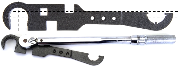
Some folks emailed regarding torque compensation for the drive offset on the combo wrench. Actually, the placement of the drive slot on the wrench handle and the plane of the handle are irrelevant. The only requirement is that the torque wrench handle be rotated to a start position where the longitudinal axis of its handle bisects the diameter of the wrench’s jaws. The distance from the center of the jaws to the center of the drive must be factored in when calculating wrench torque setting compensation.

T= Wrench Torque setting or reading.
L= Length in inches from center of drive to mid point of grip.
E= The distance from wrench drive center to fastener center
as measured parallel to the wrench handle.
In this case, the desired torque is 50 ft-lbs, the grip is 16″ from the center of the torque wrench drive and the center of the faster is 2″ from the torque wrench drive. The torque setting should be 44.4 ft-lbs to set the barrel nut at 50 ft-lbs.
If limited room to work requires that the extension is placed at an angle to the torque wrench handle, E needs to be calculated as the (length of extension) x (cosine of the angle). As an example, a 2″ extension set at a 45º angle to the torque wrench calculates to a 1.4″ extension, the parallel distance from the torque wrench drive to the center of the fastener. 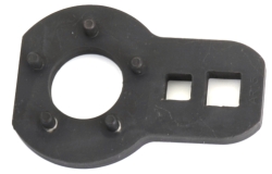 The same dimension could have been found by placing a square along the longitudinal axis of the torque wrench handle and then measuring the distance from the center of the torque wrench drive to the center of the extension jaws using the right angle of the square as the reference surface.
Alternatively, you could just buy a Precision Reflex Industries barrel nut wrench (left), Brownells # 714-000-007 $25. The wrench provides deeper and more squared engagement and it is more compact.
Bolt and carrier pieces
The JP Enterprises Supermatch™ barrel used for this build came with a JP EnhancedBolt™. The bolt was headspaced to the barrel as part of the assembly. The bolt is made of SAE 9310 high grade steel for extended life, it works with all mil-spec bits and pieces for the sake of compatibility.
The JPBC-2 full mass, stainless steel carrier is machined from 416 stainless steel. It has a dust cover notch and forward assist serrations and provides a 100% increase in bearing surface for smoother operation. Compared to a corresponding mil-spec part, the JP carriers provides improved alignment and lower wear in the upper receiver. The finish is QPQ (Quench, Polish, Quench) hard coat. This particular carrier ships with ejector, extractor and key.
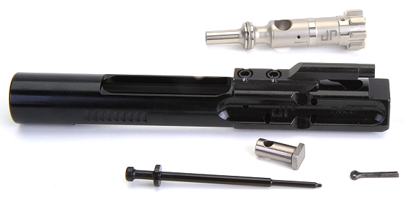
Since the bolt was bundled with the barrel and the carrier was not a complete assembly, I needed a few small pieces to put it all together – firing pin, cam pin and retainer pin. I was going to use all JP parts in the assembly, however, these three pieces were not available. This gave me the opportunity to try mixing other quality manufacturers mil-spec pieces.
The firing pin is from Rubber City Armory. It is made of 17-4 Stainless Steel that has been heat treated to 40-44RC and subjected to a black nitride process – Brownells #100-012-435 $15. The cam pin is a WMD Guns piece. The NiB-X coating is nickel boron, and yields a smooth, harder-than-chrome surface. Friction is reduced and the piece is reportedly impervious to corrosion and abrasion. Brownells #100-009-957 $10. The retainer pin is a High Standard piece, Brownells #430-000-452 $2.
The bolt assembly is supplied with three gas rings installed. About the only prep needed prior to installation in the carrier is that each of the gas ring splits (1) needs to be rotated away from the other to prevent a break in the gas ring seal and the gas rings get one drop of oil. For anyone who has installed a set of automotive pistons and rings, the process will be familiar.
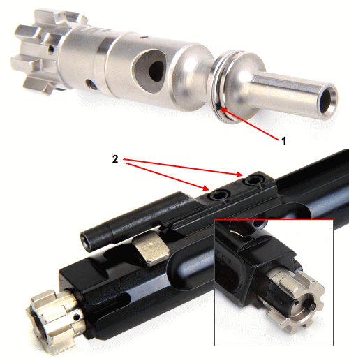
The carrier key is supplied with the carrier, installed in place and punch staked in two places at each fastener head (2). The bolt is inserted in the carrier, extractor right, ejector left, and the cam pin is dropped in through the carrier and into the bolt, then rotated into place to provide a through hole for the firing pin.
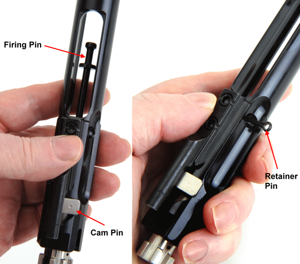
The rest of the carrier – bolt assembly is pretty straight forward. The cam pin is rotated so that the hole in its shaft will allow the firing pin to pass through. The firing pin is dropped into place and the retainer pin is inserted, left to right, to secure the firing pin. Couple of notes – the retainer is a hardened piece made for this application. A cotter pin cannot be substituted. After assembly the bolt should be inverted and the firing pin checked to assure it moves freely.
The rest of the upper assembly…
OK, I usually don’t buy G.I. Joe pieces when I assemble an AR. I was in the Air Force and lived on a flight line where small arms weighed 500 lbs, so what do I know about this type of firearm? I also think these products are made for you younger kids… you know, anyone under 50 years of age. Still, I do have excellent taste….

This particular Bravo Company charging handle model is released and actuated with a single catch by the support side hand without breaking the right side firing grip. After years of tangling my fingers between scope eyepieces and charging handles, this was too good to pass up. Brownells # 100-005-369 $48. This is a medium latch, however, there are also small which duplicates the width of the mil-spec part, large and ambidextrous latches.
The charging handle was inserted and checked for clearance over and around the gas tube. The handle was partially withdrawn, the barrier was inserted and then the assembly was pushed forward to check for bolt lock up in the barrel extension. Little effort was required.
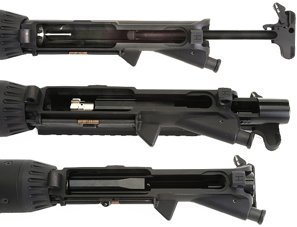
Finished upper…

With a few more small pieces on the way is, changes made to the build, we’ll take break and work on some other project, but we’ll get back on this shortly.
Your Perfect Rifle… Some Assembly Required Part 1
Your Perfect Rifle… Some Assembly Required Part 2
Your Perfect Rifle… Some Assembly Required Part 3
Your Perfect Rifle… Some Assembly Required Part 4
Your Perfect Rifle… Some Assembly Required Part 5
Your Perfect Rifle… Some Assembly Required Part 6
Your Perfect Rifle… Some Assembly Required Part 7
Your Perfect Rifle… Some Assembly Required Part 8

Email Notification