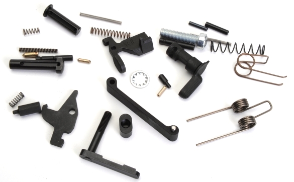
An AR15, much more so than their distant bolt action cousins, are full of … stuff and, surprisingly, most of it is necessary. In fact, when you build an AR from scratch, you have to purchase all of it. Parts are available individually and in associated parts kit form, like this Lower Receiver Parts Kit from DPMS, Brownells #231-000-258 $36. This kit includes: trigger spring, trigger pin, hammer spring, hammer pin, disconnector and spring, bolt catch, bolt catch plunger, bolt catch spring, bolt catch roll pin, selector, selector detent, selector detent spring, (2) takedown detents and springs, pivot pin, rear takedown pin, buffer retainer and spring, magazine catch, button and spring, screw and washer, trigger guard assembly and pin.
If you build ARs with some frequency, and mixing kits and individual enhanced versions of some of the parts contained in those kits, it’s good to buy kits that are specific to our needs. As an example, in addition to the kit pictured above, DPMS also offers a $30 lower receiver kit that includes a grip but no trigger pieces and a $60 kit that includes all of the parts above, plus trigger and hammer related pieces for $60. Unless specifically identified with a part number in the following text, all of the parts indicated are included in the Brownells #231-000-258 kit.
Magazine Catch
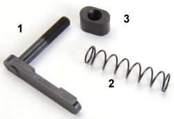 Magazine catch pieces are installed into the lower receiver first. 1. magazine catch, 2. magazine catch spring and 3. magazine catch button.
Fundamentally, the catch is slipped through its cross hole location from the left hand side of the lower receiver, the catch spring then is slipped over the catch shaft from the right side of the receiver and the catch button is pushed into the magazine catch’s right side recess.
A protected tipped punch can be used to compress the spring, and to hold the button bottomed in the receiver recess and against the catch while the catch is rotated clockwise and threaded into the button. The assembly is secure when the end of the threaded shaft is flush with the top of the button’s threads.
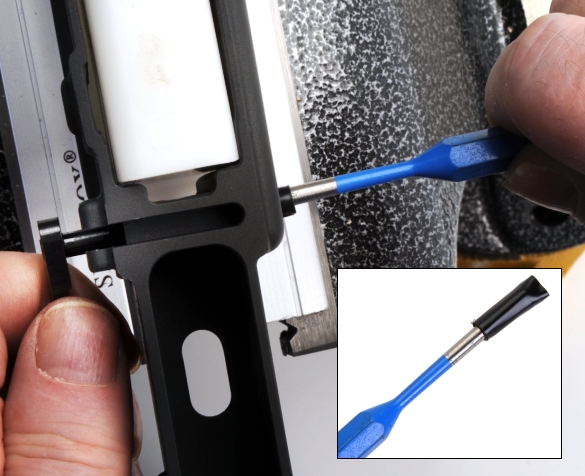
During the assembly process, it is helpful to keep some duct tape around to place on the receiver when you are going to install a part that could mar the receiver finish by contact. In this case, if care isn’t taken, the backside of the rotating catch cut into the finish if they come in contact. A little tape can also protect against the sides of punches and hammers making incidental contact.
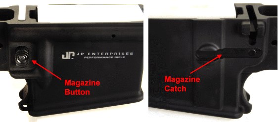
When complete, the magazine catch assembly should look about like this from the outside of the receiver, with the exception of the lettering. The button should depress and return without drag or binding. The greatest caution? Don’t scrape the receiver when screwing in the catch.
Bolt Catch
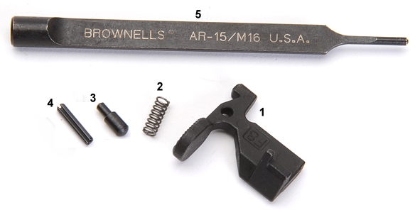
The bolt catch assembly is comprised of four parts: 1. Bolt Catch, 2. Bolt Catch Spring, 3. Bolt Catch Plunger, 4. Bolt Catch Roll Pin, 5. Brownells #080-216-012 $16. The punch is scalloped… which for some reason makes me think of deep frying and bacon wrapping. In any event, the punch instructions indicate it is used to remove the roll pin by driving it to the rear. Brownells “How to Build an AR-15” suggests the cutaway punch can also be used to install the bolt catch roll pin from the front without marring the lower receiver or smacking the pin at an angle.
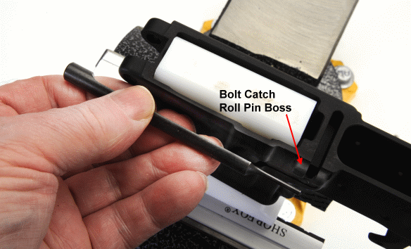
Every other source of instruction for AR-15 assembly indicates that the roll pin should be installed from rear to front, but then they don’t indicate the use of this cutaway punch. So I figured, “What the heck, it’s only money”, so I closed my eyes, thought better of it, opened my eyes, and then proceeded.
Basically, the bolt catch spring and the bolt catch plunger are plopped into the detent recess in the side of the receiver, the bolt catch is placed in position and a #3 roll pin punch or suitable substitute is inserted back to front through the receiver’s pin boss to hold all of the parts in place. A little tape goes a long ways toward eliminating handling marks from errant hammer and punch strikes.
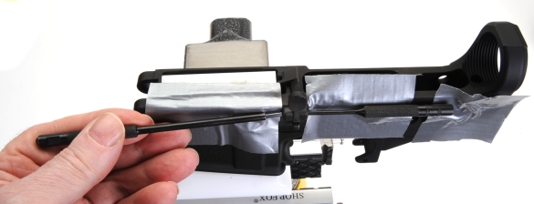
The only problem I found with the front to rear roll pin installation was starting the pin with a roll pin holder as presented in “How to Build an AR-15”. No matter how close the holder is held to the receiver, the pin still starts at an angle. The contact is brief, as a switch is made to the Bolt Catch Pin Punch as soon as the roll pin is started, but it is an awkward approach. Maybe a flat sided #3 roll pin holder is in order? The #1 in a set is already flat cut at the tip. Or maybe the roll pin should just be inserted from the rear and the Bolt Catch Pin Punch should be reserved for pin removal only?
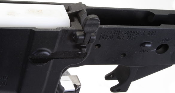
The lower receiver should look something like this after the bolt catch is installed. The part is checked for full travel, freedom of movement and, perhaps, association. When a roll pin is tapped upon with a punch and 4 ounce hammer, it tends to get a little bright where struck regardless the punch material. A Birchwood Casey flat finish Super Black Instant Touch Up Pen, Brownells 167-004-190 $8 can clean up these minor imperfections on surfaces not exposed to contact friction.
Pivot pin installation… Sure, why not?
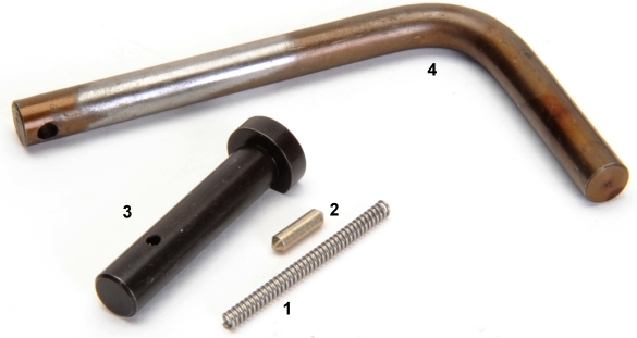
The pivot pin installation is the cosmic culmination of: 1. Pivot Pin Detent Spring, 2. Pivot Pin Detent, 3. Pivot Pin, 4. Pivot Pin Detent Installation Tool – Brownells #080-216-011 $16. Lessons quickly learned; the tool is cheap for what it does and there is a reason why detent springs are sold in three packs.

Left to right, the detent well in the front of the lower receiver. The tool in place through the pivot pin bosses on the receiver, the hole in the tool lined up with the hole in the receiver and the detent spring inserted through the tool and into the receiver. Right, the detent pin inserted through the tool.
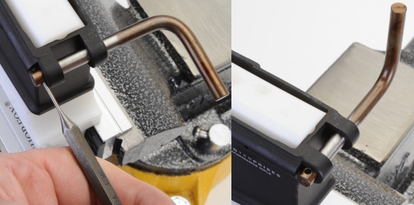
A punch is used to depress the detent… not emotionally as much as conditionally, so that the detent has exited the tool, but the punch has not entered the detent well in the receiver. The tool is then rotated which moved the hole out of index with the detent, retaining the detent in a compressed state.
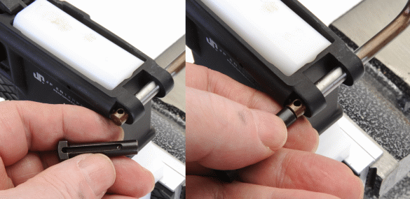
Above, the receiver side of the pivot pin has a channel that the spring loaded detent rides in and a flat machined on the head of the pin. Installed, the detent rides in the slot, allowing the pivot pin to be pulled out far enough to free the upper receiver, but not far enough for the pivot pin to pull free of the lower. To install initially, the pivot pin is indexed with the flat facing the receiver and then the pin is lined up with the pivot pin detent installation tool. The pin is used to drive the tool through and out of the pin bosses at the front of the receiver. Held firmly, the detent will stay in place in the receiver and lock into the pivot pin. Held loosely while displacing the detent install tool, the detent and spring will pop out as soon as they clear the end of the tool.
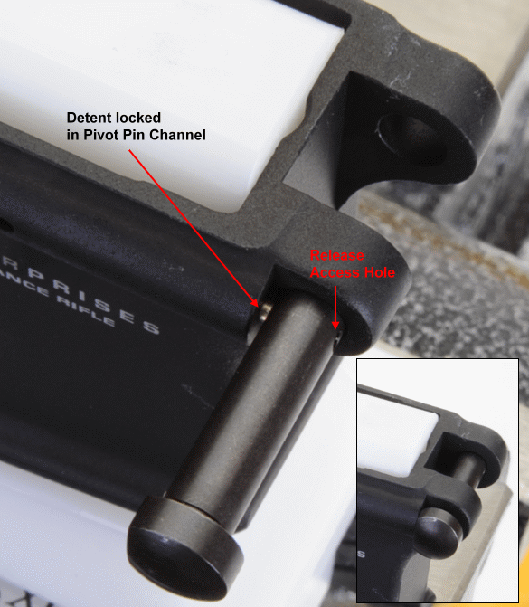
Above, the pivot pin in place retaining the spring loaded detent. The pivot pin is removed from the receiver by inserting a narrow punch or removal tool into the access hole and depressing the detent.
Time to take a break and catch up on other projects. Next, trigger and safety installation. Again, the intent is not to provide step by step assembly instructions, but rather to provide an overview of the process for folks who might be considering putting their own AR together.
Your Perfect Rifle… Some Assembly Required Part 1
Your Perfect Rifle… Some Assembly Required Part 2
Your Perfect Rifle… Some Assembly Required Part 3
Your Perfect Rifle… Some Assembly Required Part 4
Your Perfect Rifle… Some Assembly Required Part 5
Your Perfect Rifle… Some Assembly Required Part 6
Your Perfect Rifle… Some Assembly Required Part 7
Your Perfect Rifle… Some Assembly Required Part 8

Email Notification